Smoothing roller in a printing unit of a rotary printing machine

Inactive Publication Date: 2002-05-21
MANROLANAD AG
View PDF32 Cites 4 Cited by
  • Summary
  • Abstract
  • Description
  • Claims
  • Application Information

AI Technical Summary

Benefits of technology

This object is achieved by a smoothing cylinder applied to a form cylinder in a printing unit of a rotary printing machine or applied to an ink applicator roller, wherein an outer surface of the smoothing roller has an ink-repelling effect.
In a preferred embodiment, a transfer of printing ink onto the smoothing roller is prevented by appropriately designing the latter. The result of this, in particular, is that, in a nib between the form cylinder and the smoothing roller or between the ink applicator roller and smoothing roller, the ink film is merely squeezed and not split. Since the surface of the smoothing roller has an appropriately smooth design, the ink film thereby assumes a markedly more homogeneous structure, that is to say greater smoothness.
In a further embodiment, an improvement is obtained if the smoothing roller is not driven by friction with the ink applicator roller or form cylinder, but is provided with its own drive. The rolling conditions between the smoothing roller and ink applicator roller or form cylinder can thereby be improved for exerting an additional smoothing effect on the ink film. The ink-repelling effect of the smoothing roller may be achieved by coating the smoothing roller with a material which is coordinated with the printing ink used. In the case of waterless offset printing, this coating may include a silicone coating, such as is present in the print-free regions of the printing form.
Furthermore, the ink-repelling smoothing roller may, in the case of dry offset printing, comprise material or a coating having an affinity to silicon oils for absorbing the silicone oil fractions from the printing ink. The smoothing roller with this property forms a film which leads to a uniform ink film on the ink applicator roller or form cylinder. In addition, when the smoothing roller is applied onto an link applicator roller, the affinity of the smoothing roller to silicon oil causes the absorption of excess silicone oil and leads to a uniform distribution of the silicone oil fraction in the ink film. The silicone oil excess is absorbed by the smoothing roller and is redistributed to other regions of the ink applicator roller. The same likewise applies accordingly to the silicone oil substitute or when dampening medium has previously been mixed into the printing ink.
The smoothing roller is set axis-parallel to the ink applicator roller or the form cylinder, but may also be set obliquely, with the result that additional distribution of the printing ink layer occurs.

Problems solved by technology

Irrespective of whether a printing ink has to contain a separating agent in order to be particularly suitable for dry offset printing or whether printing is carried out using a dampening medium, there is the problem, particularly in the case of short inking units, of obtaining as smooth an ink film as possible on the form cylinder, in order to achieve high printing quality.

Method used


Image

  • Smoothing roller in a printing unit of a rotary printing machine
  • Smoothing roller in a printing unit of a rotary printing machine
  • Smoothing roller in a printing unit of a rotary printing machine

Examples


Embodiment Construction

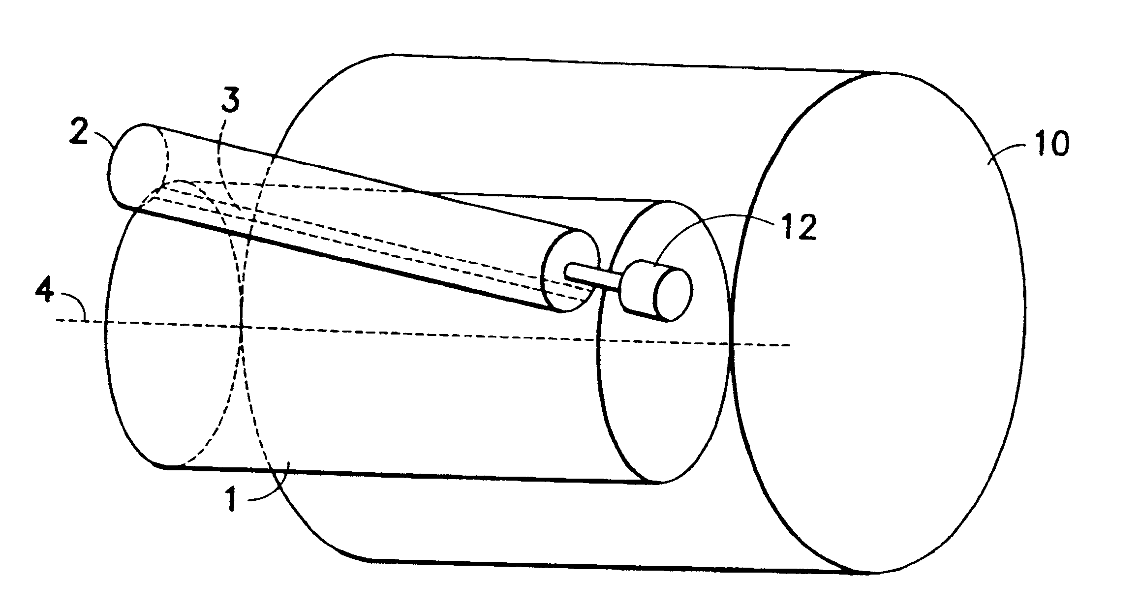
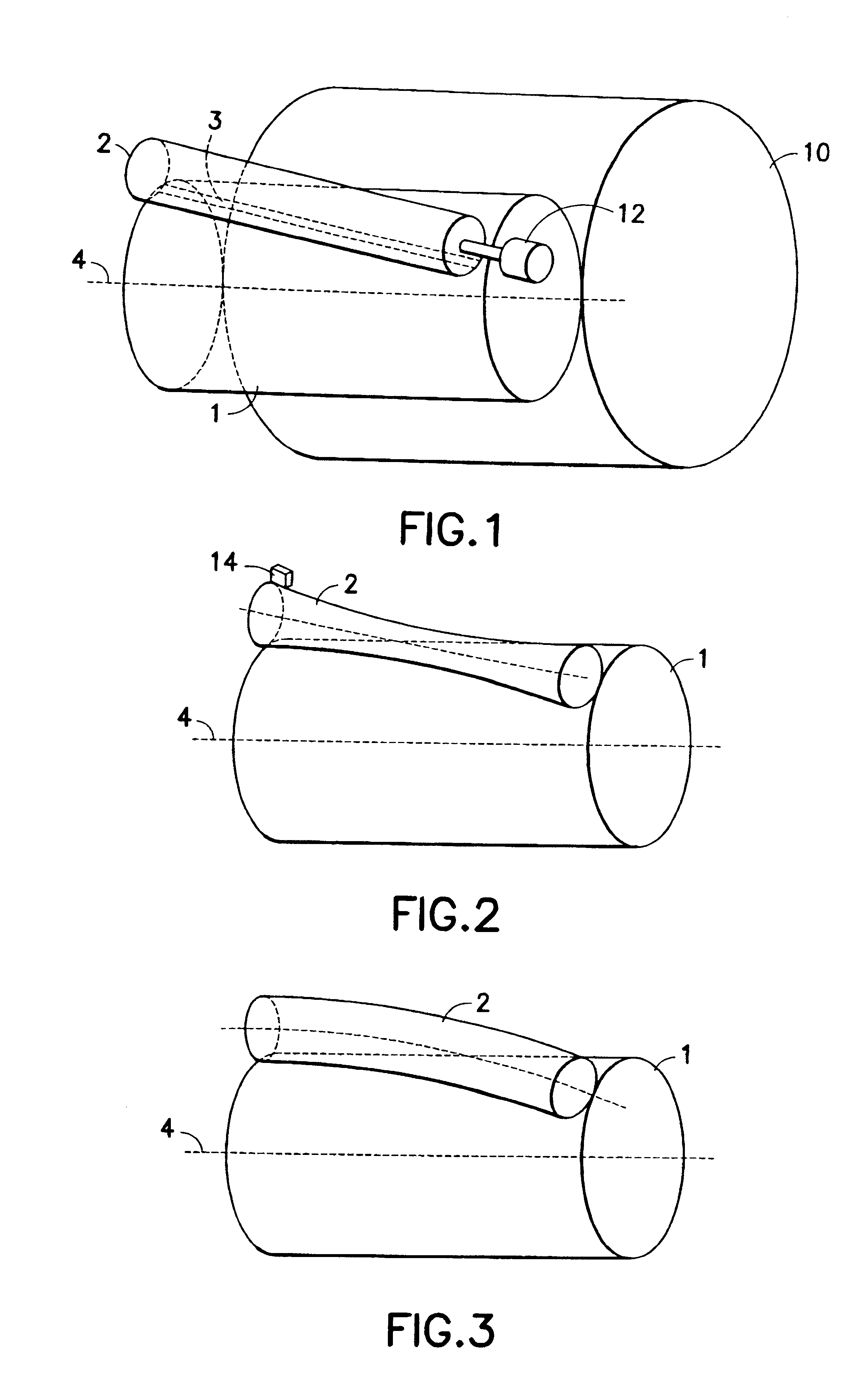
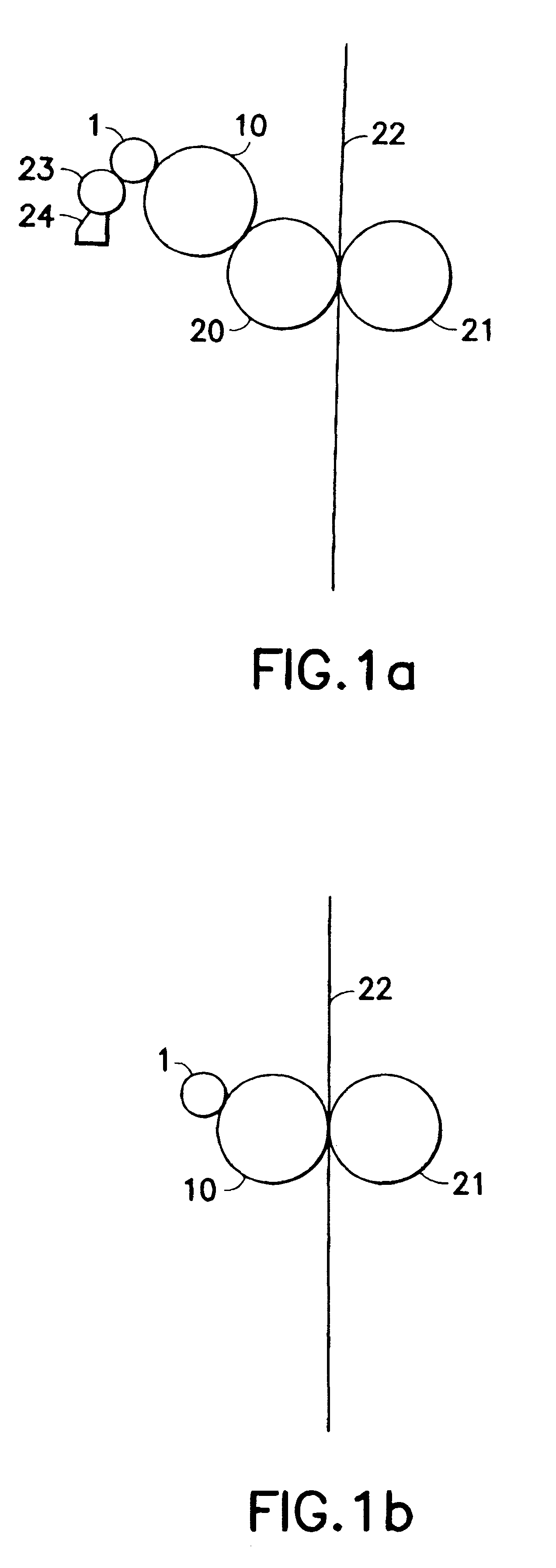
Referring to FIG. 1, an ink applicator roller 1 according to the present invention is arranged on a form roller 10 in an inking unit of a printing machine such, for example, as a short inking unit of an offset printing machine or a printing machine for direct printing. FIG. 1a shows an example of how the applicator roller 1 and the form roller 10 may be arranged in an offset printing machine. In this example, a transfer roller 20 such as, for example, a blanket roller, is arranged between the form roller 10 and an impression roller 21 for printing onto a web 22 which runs between the transfer roller 20 and the impression roller. FIG. 1b shows an example of how the applicator roller 1 and the form roller 10 may be arranged in a direct printing machine in which the form roller 10 directly contacts the web 22 for printing thereon. As shown in FIG. 1a, the ink applicator roller 1 is part of an inking unit such as, for example, a short inking unit comprising an ink transfer roller 23 and...


PUM


Abstract

The present invention provides a smoothing roller for a printing unit of a rotary printing machine. The smoothing roller is applied to the form cylinder downstream of the ink applicator roller in relation to the direction of rotation of the form cylinder or onto the ink applicator roller itself. The smoothing roller smooths the ink film on the form cylinder or on the ink applicator roller. The outer surface of the smoothing roller has an ink-repelling characteristic. The ink-repelling characteristic is effected by a liquid ink-repelling material such as a separating agent or a dampening medium that is applied to the outer surface of the smoothing roller or by an outer surface of the smoothing roller comprising an ink-repelling material. The two measures for effecting the ink-repellant characteristic of the smoothing roller may also be provided in combination with one another.

Description

1. Field of the InventionThe invention relates to a smoothing roller in a printing unit of a rotary printing machine.2. Description of the Related ArtReference DE 44 24 913 A1 discloses a short inking unit for the inking of a form cylinder for dry offset printing. The short inking unit has an ink transfer roller and an ink applicator roller. The ink transfer roller is designed as a screen roller. Between the depressions on the outer surface of the screen roller there are webs which have high affinity to a separating agent, for example silicone oil. For this purpose, the hard-ceramic material of the ink transfer roller is impregnated with silicone oil, or silicone rubber or fluorosilicone rubber is embedded into the hard-ceramic material. The depressions are lined with an ink-friendly coating repelling the separating agent. The design of the ink transfer roller is intended to avoid ink transfer difficulties when using inks mixed with a separating agent.Reference DE 44 24 920 A1 discl...

Claims


Application Information

Patent Timeline
Patent Type & Authority Patents(United States)
IPC IPC(8): B41F31/00B41F31/14B41F31/26
CPCB41F31/00
Inventor BACHMEIR, XAVERFISCHER, WOLFRAMFELLER, BERNHARD
Owner MANROLANAD AG
Why Eureka
Try Eureka