Method of controlling a frequency converter of a reluctance machine

a technology of reluctance machine and frequency converter, which is applied in the direction of motor/generator/converter stopper, dynamo-electric converter control, starter details, etc., can solve the problems of difficult in practice and expensive, harmful noise problems, and occasional noise problems

Inactive Publication Date: 2002-05-21
ROBERT BOSCH GMBH
View PDF6 Cites 2 Cited by
  • Summary
  • Abstract
  • Description
  • Claims
  • Application Information

AI Technical Summary

Problems solved by technology

This leads to unpleasant and in some cases harmful noise problems.
However the clock frequency must generally be measured, which is difficult in practice and is expensive.
However because of the constant clock frequency noise problems occasionally occur.
The problem is that the components and the circuit losses limit the maximum possible clocking frequency.

Method used


Image

  • Method of controlling a frequency converter of a reluctance machine
  • Method of controlling a frequency converter of a reluctance machine

Examples


Embodiment Construction

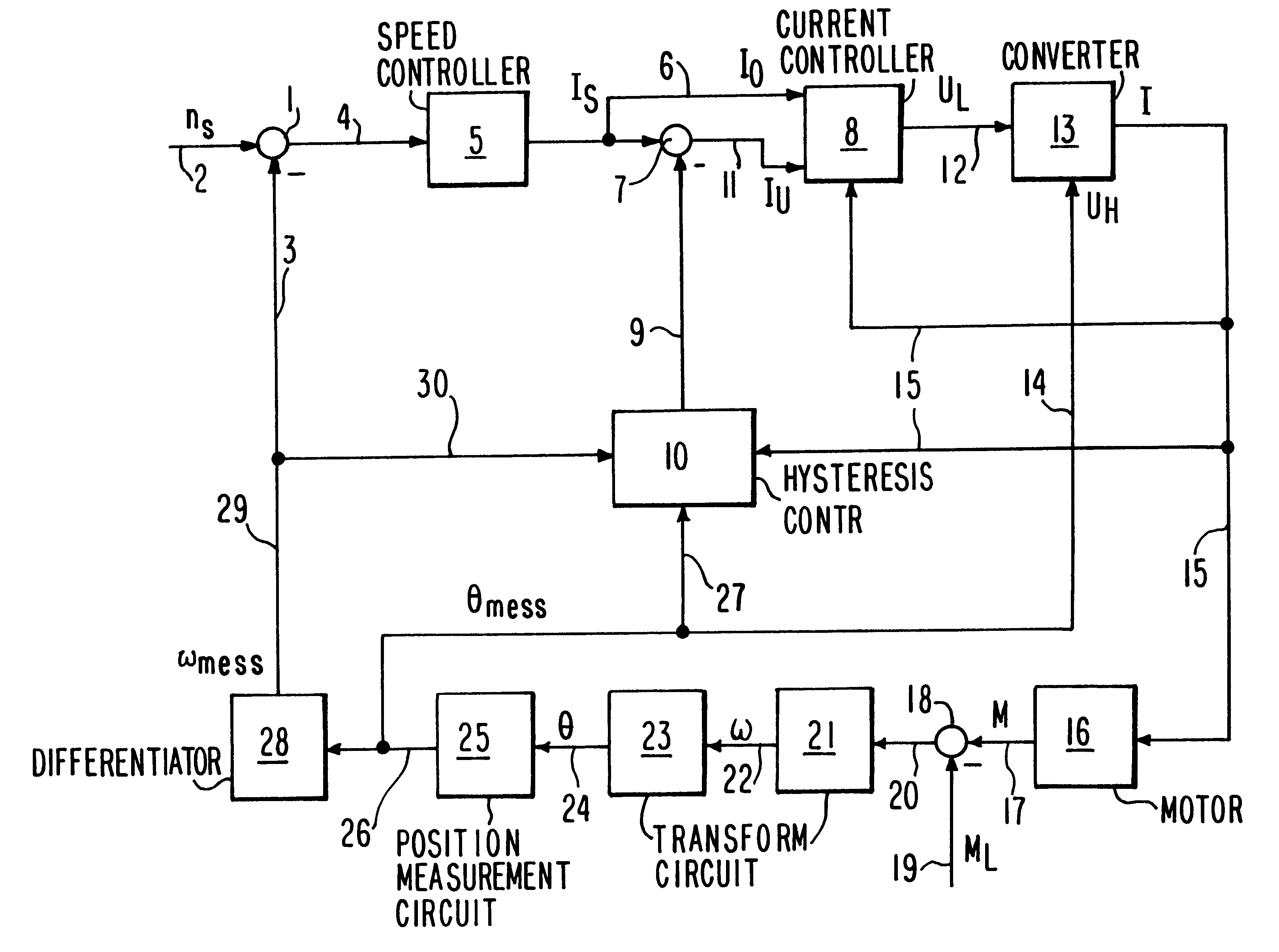
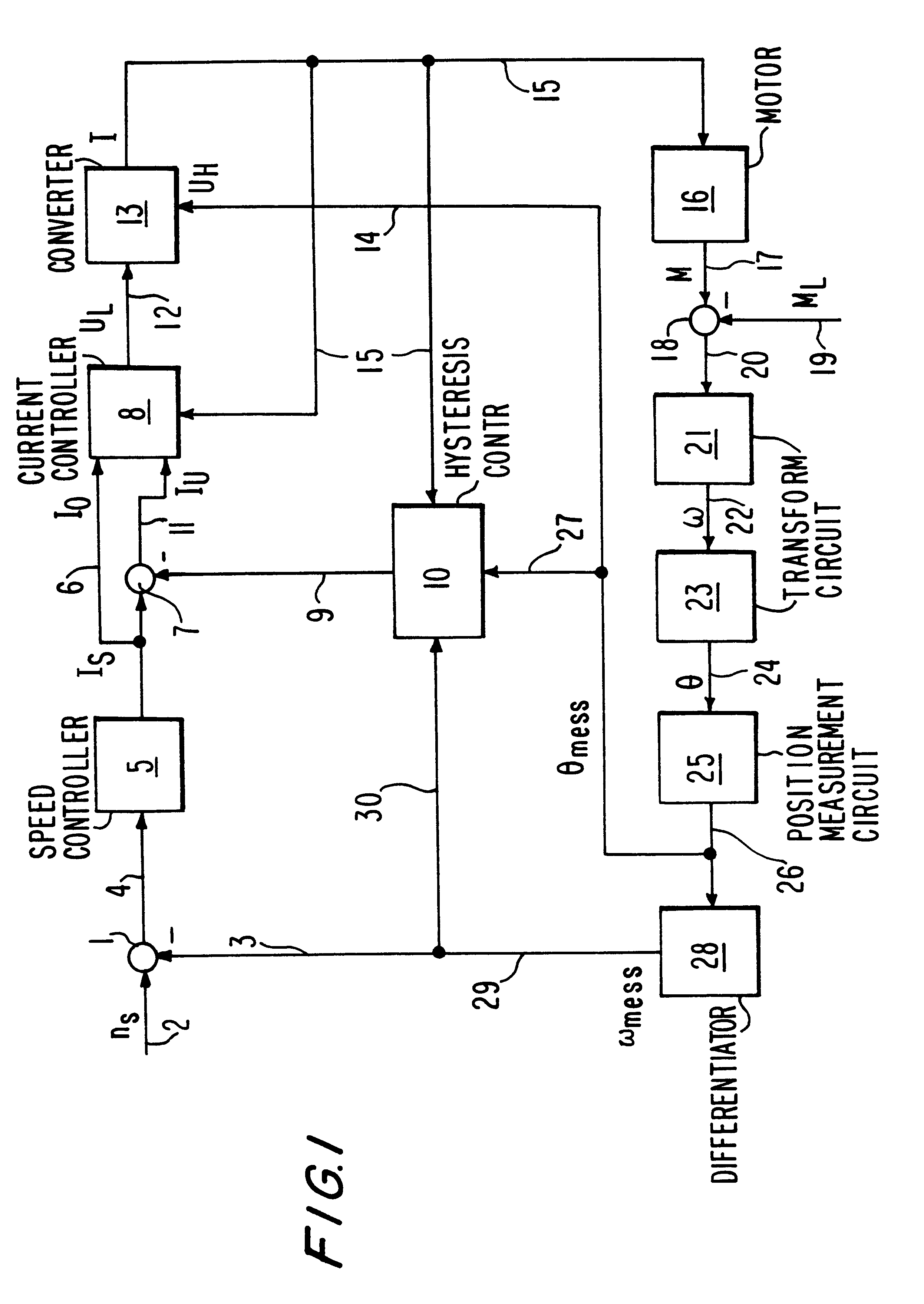
A set rotation speed n.sub.s is input to a summation point 1 with a positive sign on a line 2 and a measured rotation speed .omega..sub.mess is input to the summation point 1 with a negative sign on line 3 for rotation speed regulation. The resulting difference is supplied to a rotation speed controller 5 on a line 4. The rotation speed controller 5 converts this input into a set current value I.sub.s, which for example can correspond to the upper current threshold value I.sub.o of the hysteresis band. It is then supplied over the line 6 to both a current controller 8 and a second summation point 7 as the upper current set value I.sub.0 and as an input signal for the second summation point 7 respectively. An output signal from the hysteresis controller 10, which represents a current correction value, is fed to the second summation point 7 over the line 9 with the negative sign. A difference signal, which is fed over a line 11 to the current controller 8 as a second input signal I.su...


PUM


Abstract

The method of controlling a converter of a switched reluctance machine includes clocking a power switch with a frequency that depends on the width of the hysteresis band. The hysteresis width is varied according to reluctance machine speed, especially so that a difference between maximum and minimum values with which the current is switched on and off either increases with decreasing speed, decreases with increasing load, or both. The changing of the hysteresis width occurs so that a difference between maximum and minimum threshold values either increases with decreasing speed, decreases with increasing load, or both. The width of the hysteresis band preferably varies linearly with speed, load and / or current, especially so that the width of the hysteresis band varies linearly so that the clocking frequency is maintained substantially constant. Also targeted changes in the width of the hysteresis band are made to move the clocking frequency from near noise-critical resonance frequencies.

Description

1. Field of the InventionThe present invention relates to a method of controlling a frequency converter of a switched reluctance machine, which includes current regulation with hysteresis, with which the current switch is clocked with a frequency, which depends on the width of a hysteresis band.2. Prior ArtDifferent methods for controlling a frequency converter for a switched reluctance motor are described in Chapter 4, Dynamic Operation, on pp. 53 to 61 of the book "Switched Reluctance Motors and Their Control" by T. J. E. Miller, MAGNA PHYSICS PUBLISHING AND CLARENDON PRESS, OXFORD, 1993. A frequency converter circuit, which provides a switch for the current supply, a commutator switch and two free-running diodes associated with these switches for each phase of the machine, is usually used. The switches usually comprise transistors. One such switch is shown, e.g. in FIG. 4.1 on page 53 of the above-mentioned reference. These switches can be operated in both a hard and also soft in...

Claims


Application Information

Patent Timeline
Patent Type & Authority Patents(United States)
IPC IPC(8): H02P25/08H02P25/02H02P25/092
CPCH02P25/082H02P25/0925
Inventor HEESE, THOMAS
Owner ROBERT BOSCH GMBH
Why Eureka
Try Eureka