This helps you quickly interpret patents by identifying the three key elements:
Problems solved by technology
Method used
Benefits of technology
Benefits of technology
Another object of the present invention is to provide a fluid flowing control device comprising a valve which can generate a large amount of velocity head loss on a plurality of fluid flowing paths to thereby increase a tortuous section per the fluid flowing path under the constant pressure drop, whereby the fluid flowing path is not blocked by the foreign materials passing through the valve to thereby increase an amount of the fluid flow within a predetermined volume thereof.
Problems solved by technology
In the conventional cage for utilizing as a valve, the size of the cage becomes bulky because of the small fluid flowing path and the simple tortuous path formation for generating the required amount of velocity head loss.
In addition, a vena contracta phenomenon caused by an orifice principle occurs in the vicinity of the sealing portion thereof or a clearance resulting in the cavitation, flashing, erosion / corrosion, noise and vibration caused due to velocity increment of fluid flow and decrement of the pressure on the fluid flowing resistor, plug, seat and the like.
On the other hand, since the cage comprises a plurality of fluid flowing paths having the sectional area so as to generate the desired amount of velocity head loss if foreign materials are inserted into the inlet of the valve, the paths of the cage or the inlet thereof are blocked which thereby deteriorates the inherent performance of the valve.
Meanwhile, in the valve where the fluid passes through the cage from the lower portion of the plug, the sealing portion of the leading end of the plug, which is moved in an axial direction, is damaged due to the foreign materials blocking up the inlet of the path of the cage, to drastically deteriorate the sealing function of the valve.
Method used
Image
Click on the blue label to locate the original text in one second.
Reading with bidirectional positioning of images and text.
Examples
first embodiment
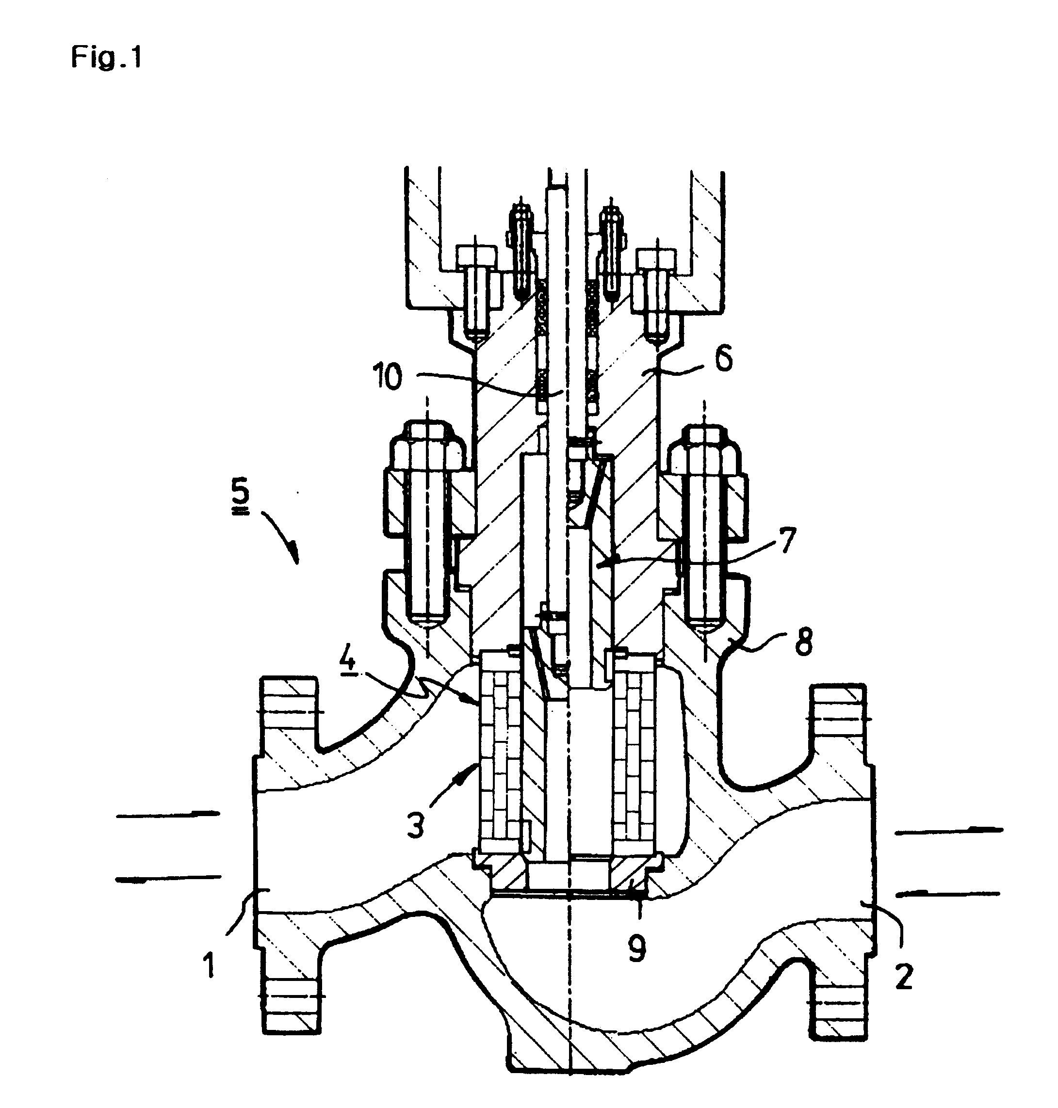
FIG. 1 is a partial sectional view illustrating a valve in which fluid flow is controlled according to the present invention;
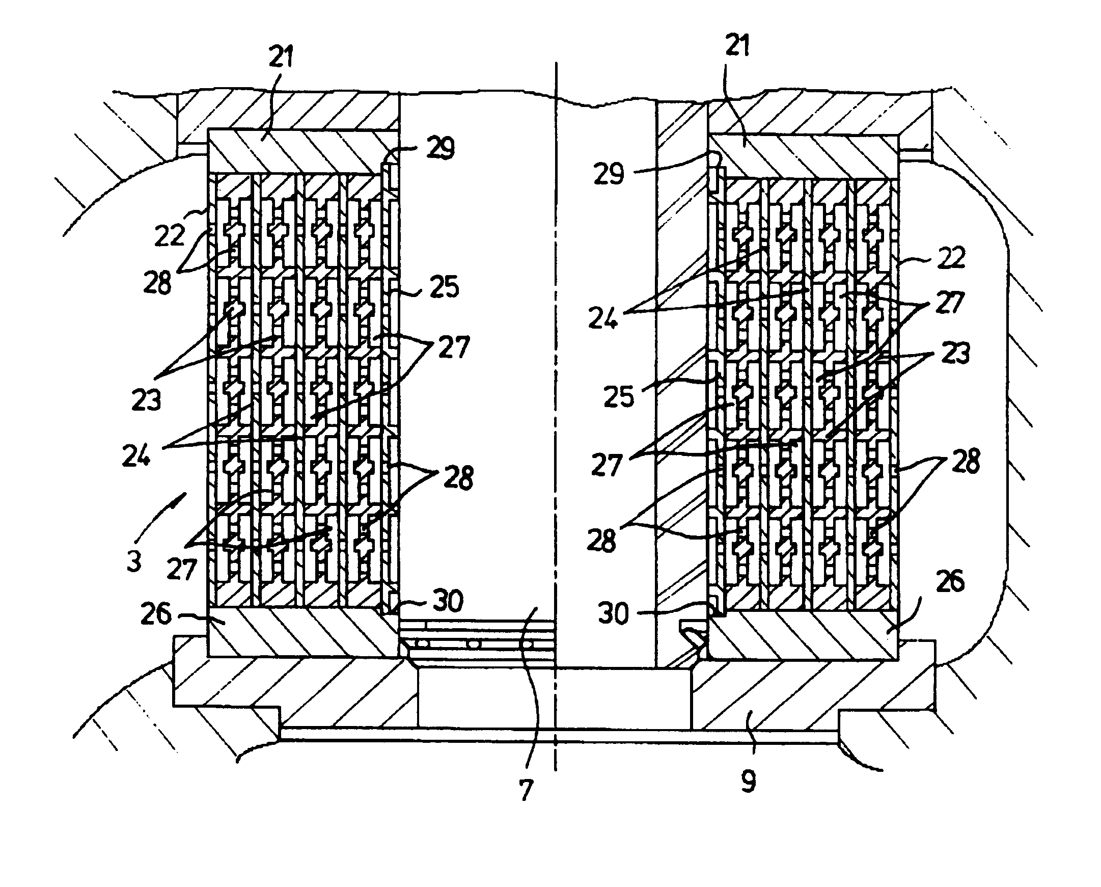
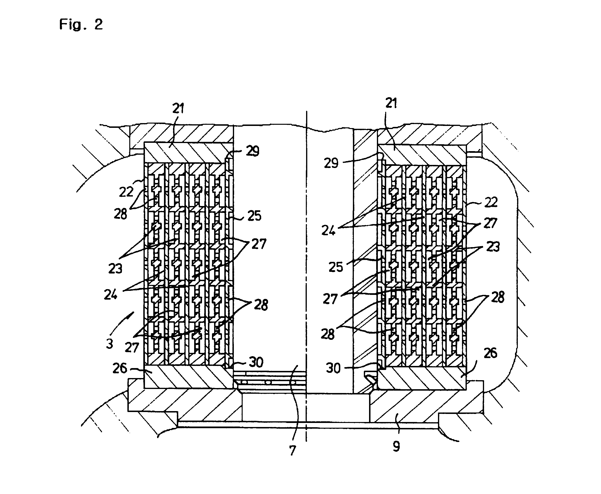
FIG. 2 is a partial section view illustrating the valve of FIG. 1, in which a cylindrical cage is installed;
FIG. 3 is a partial sectional view illustrating the arrangement of the cage of FIG. 2;
FIG. 4 is a perspective view illustrating an inside cylinder of the cage of FIG. 2;
FIG. 5 is a partial sectional view illustrating an inside cylinder having concave / convex grooves of the cage of FIG. 2;
FIG. 6 is a perspective view illustrating an outside cylinder of the cage of FIG. 2;
FIG. 7 is a partial sectional view illustrating one formation and arrangement of the inside cylinder of the cage of FIG. 2;
FIG. 8 is a partial sectional view illustrating another formation and arrangement of the inside cylinder of the cage of FIG. 2;
FIGS. 9 and 9a are partial sectional views illustrating yet another formation and arrangement of the inside cylinder of the cage of FIG. 2;
FIG...
second embodiment
FIG. 11 is a sectional view illustrating a valve in which fluid flow is controlled according to the present invention, in which a disc type column is installed;
FIG. 12 is a partial plan view illustrating a pair of discs of the disc type column of FIG. 11;
FIG. 13 is a partial perspective view illustrating the pair of discs of FIG. 11;
FIG. 14 is a partial plan view illustrating a fluid flowing path of one disc of the disc type column of FIG. 11;
FIG. 14a is a partial sectional view illustrating an operational process of FIG. 14;
FIGS. 15, 15a, and 15b are partial sectional and side views illustrating the pair of discs of the disc type column of FIG. 11;
FIGS. 16, 16a, 16b, and 16c are partial sectional views illustrating the valve of FIG. 1, in which a function separation type plug and a seat are installed;
FIGS. 17 and 17a are partial section views illustrating the separating function of the plug and the seat of FIGS. 16, 16a and 16b on which protrusion and groove are respectively formed...
third embodiment
FIG. 18 is a partial sectional view illustrating a fluid flow control device of a valve according to the present invention, where a fluid flowing resistor and seat are integrated with each other.
The fluid flowing resistor of the present invention is configured based upon a cylinder or a disc, and a resistant portion of each fluid flowing path which is constituted by combining orifice, rectangular section elbow with recess so as to produce a high amount of velocity head loss.
The rectangular section elbow of the present invention has different sectional area for the inlet or the outlet which is intended to generate a high amount of velocity head loss relative to the fluid flow.
The amount of pressure drop generated through the fluid flowing path is proportional to the loss coefficient, density of fluid and square of velocity which are determined upon the shape of fluid flowing path of the resistant portion and Reynolds number.
Since the amount of pressure drop is determined in accordanc...
PUM
Abstract
Disclosed is a fluid flowing control device of a valve having fluid flowing paths which are made in more sophisticated configuration and by controlling the velocity of the fluid by the maximal use of available volume thereof, to thereby prevent to a maximal extent the generation of cavitation, flashing, blocking by foreign materials, and the damage of internal parts. The device includes a cage having an inside cylinder which is closely contacted with a plug, an outside cylinder which forms a plurality of holes in axial and radius directions, respectively, a first internal cylinder which forms a plurality of concave / convex grooves having rectangular sectional elbows with recess in an axial direction, a second internal cylinder which forms a plurality of holes in axial and radial directions, and upper and lower supporting plates for closely coupling the inside and outside cylinders with the first and second internal cylinders on the top and bottom ends thereof; the plug forming a sealing portion and an opening / closing portion which are in contact with a seat, on the leading end of the lower portion thereof, to thereby open / close the seat and control the fluid flow, while being moved in the inside of the cage; and the seat being in internal-contact with the plug.
Description
1. Field of the InventionThe present invention relates to a mechanical technology used in the treatment for various kinds of fluids such as, for example, a compressive fluid, a non-compressive fluid and the like, and more particularly, to a fluid flowing control device comprising a valve having fluid flowing paths which are devised in a more sophisticated configuration by controlling fluid resistance, back pressure and overall operations and by controlling the velocity of fluid by the maximal use of available volume to thereby prevent the generation of cavitation, flashing, blocking by foreign materials, and the damage of internal parts.The present invention is related to a fluid flowing resistor, a back pressure control part and can be applied to a multi-orifice type valve, a multi-path type valve, or any fluid flowing control device which is similar thereto.2. The Prior ArtConventionally, the devices, which are related to valves and resistors, are applied in a wide range of fields...
Claims
Application Information
Patent Timeline
Application Date:The date an application was filed.
Publication Date:The date a patent or application was officially published.
First Publication Date:The earliest publication date of a patent with the same application number.
Issue Date:Publication date of the patent grant document.
PCT Entry Date:The Entry date of PCT National Phase.
Estimated Expiry Date:The statutory expiry date of a patent right according to the Patent Law, and it is the longest term of protection that the patent right can achieve without the termination of the patent right due to other reasons(Term extension factor has been taken into account ).
Invalid Date:Actual expiry date is based on effective date or publication date of legal transaction data of invalid patent.

