Nutcracking apparatus

Inactive Publication Date: 2002-06-04
EISEL JOSEPH D
View PDF19 Cites 29 Cited by
  • Summary
  • Abstract
  • Description
  • Claims
  • Application Information

AI Technical Summary

Benefits of technology

It is an object of the present invention to provide a nut

Problems solved by technology

However, such devices are complex, and they ten

Method used


Image

  • Nutcracking apparatus
  • Nutcracking apparatus
  • Nutcracking apparatus

Examples


Example

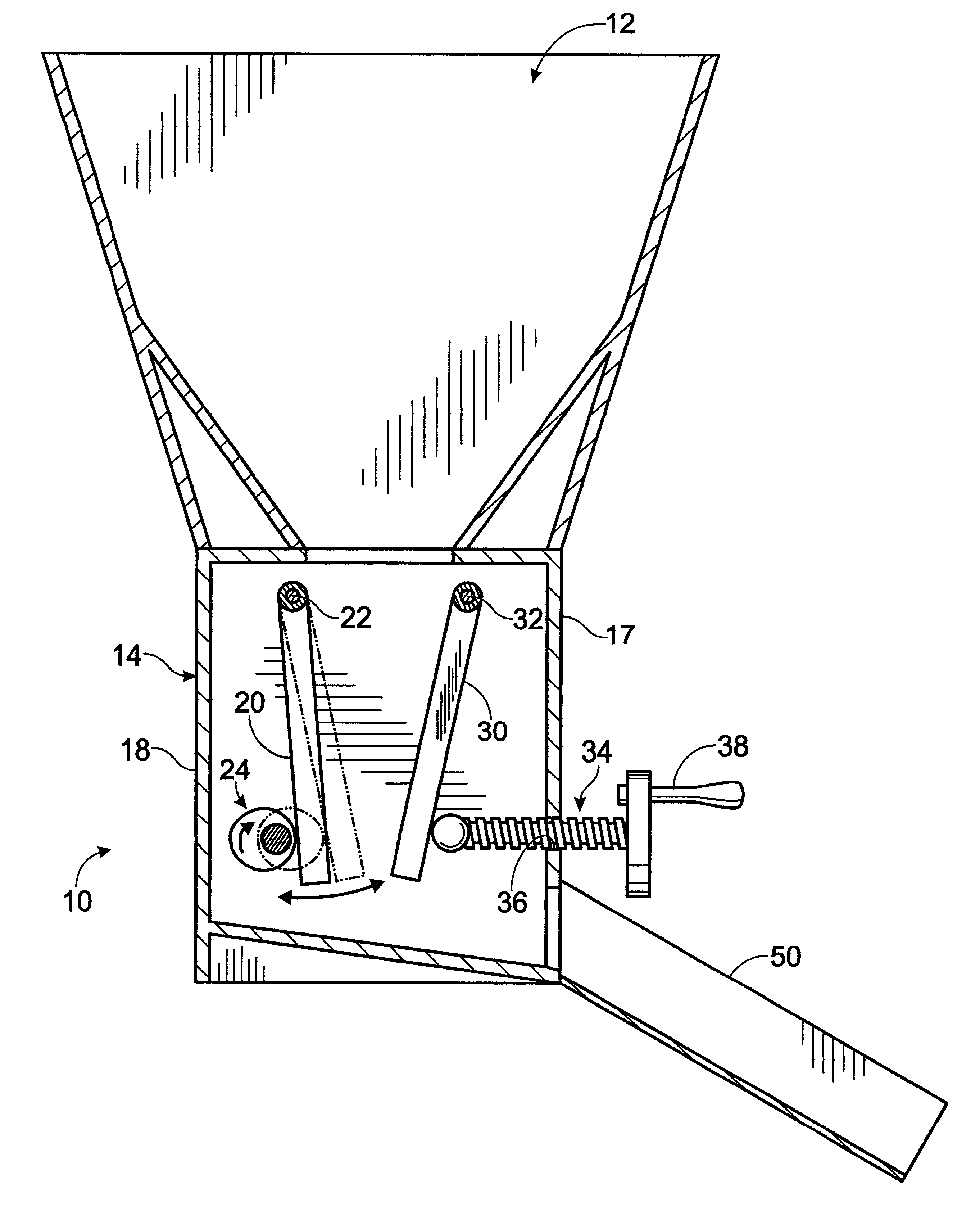
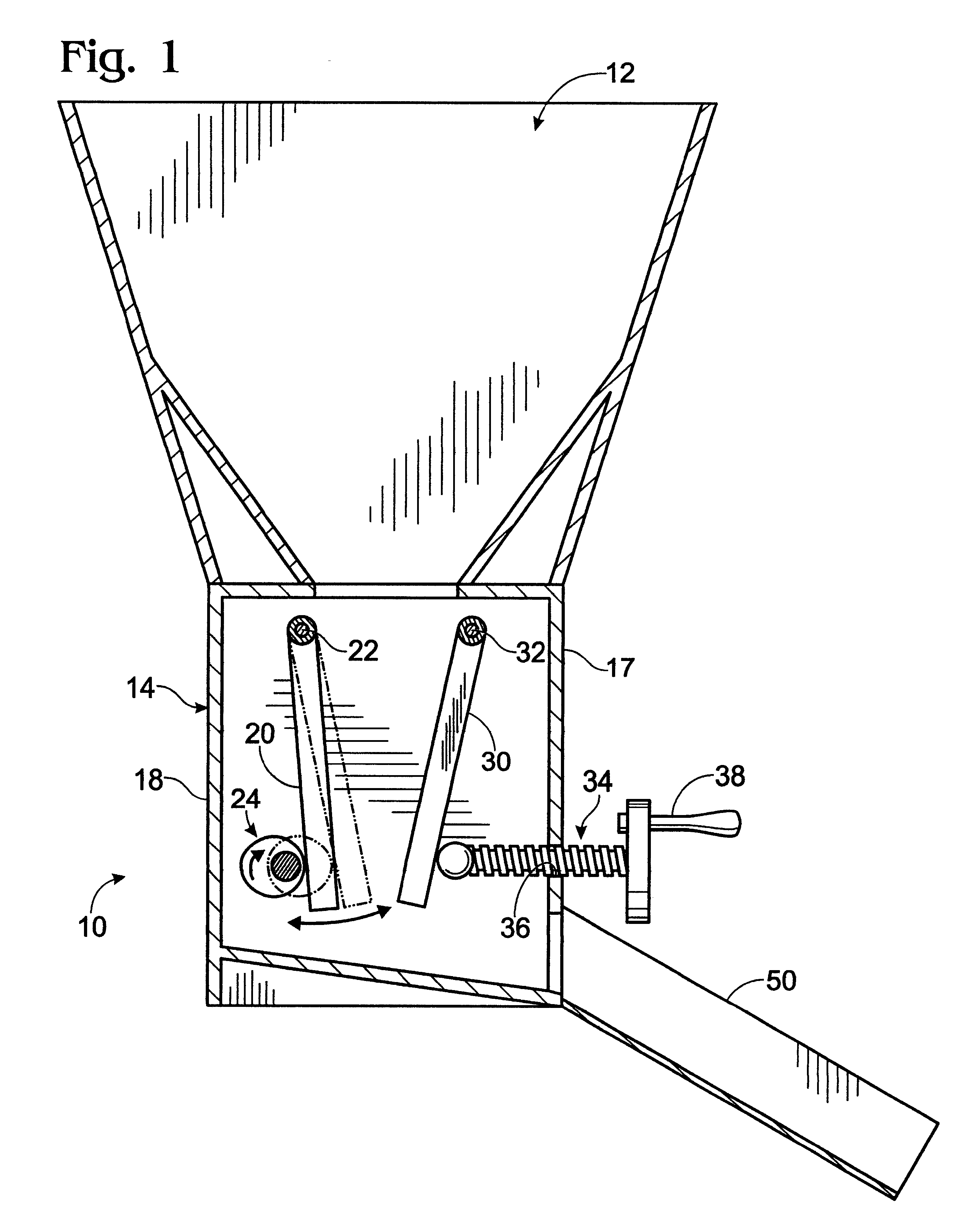
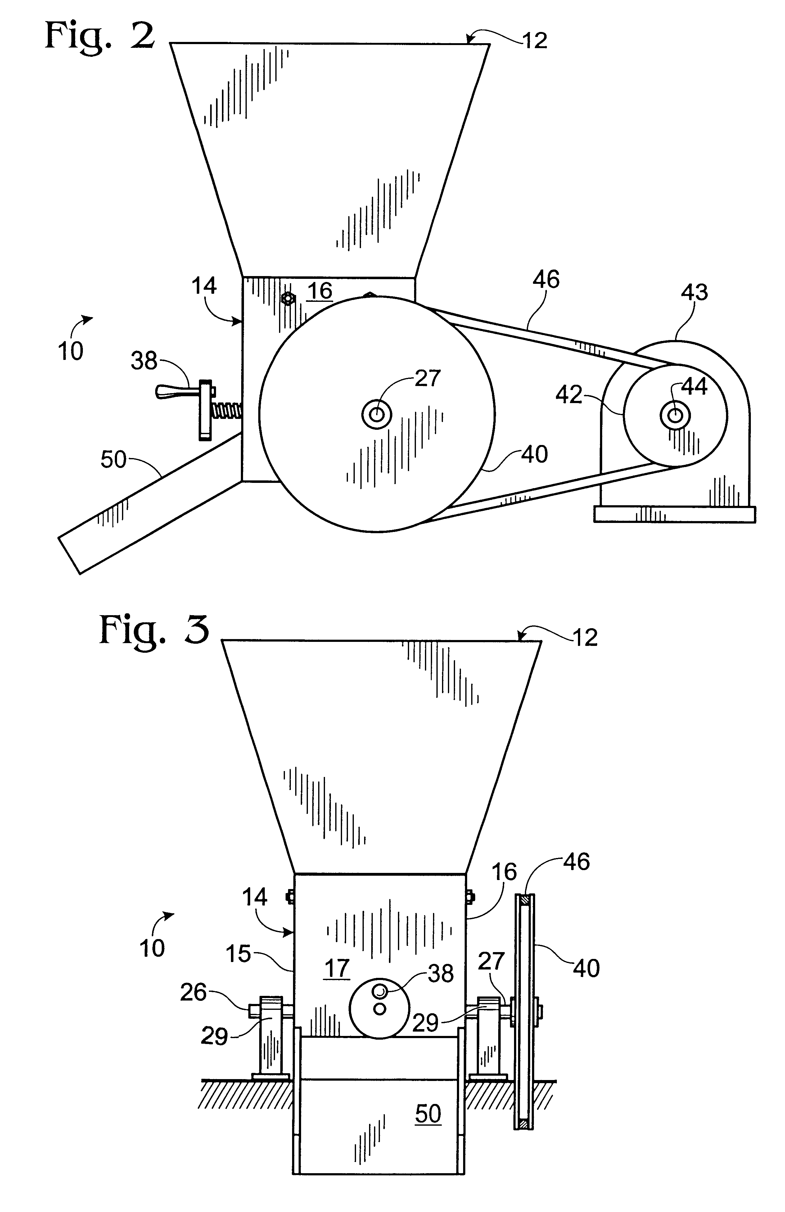
The nutcracking apparatus 10 of the present invention has a hopper 12 for receiving the nuts to be cracked. Hopper 12 communicates with the interior of housing 14. Housing 14 includes left sidewall 15, right sidewall 16, front wall 17 and rear wall 18.

Hammer plate 20 is located inside housing 14, and is attached at its upper end to axle 22. The outer ends of axle 22 are threaded and pivotally attached to opposing sidewalls 15 and 16 of housing 14, as best seen in FIG. 6. The threaded outer ends of axle 22 pass through sidewalls 15 and 16 and have locknuts 23 attached to their outer ends.

The area adjacent the lower edge of hammer plate 20 is in abutment with a camshaft 24. Camshaft 24 is positioned so that hammer plate 20 is at an angle to the vertical, and hammer plate 20 is, even when there are no nuts in hopper 12, retained in abutment with camshaft 24 by the force of gravity.

Camshaft 24 includes an axle 25 having a left outer end 26 and a right outer end 27. The right outer end 2...


PUM


Abstract

A nutcracking apparatus including a housing having opposing sidewalls. A hammer plate having an upper and lower portion is pivotally attached at its upper portion to the opposing sidewalls of the housing. A camshaft is positioned in abutment with a lower portion of the hammer plate, and a drive attached to an outer end of the cam shaft for effecting rotation thereof. An anvil plate having an upper and lower portion is spaced from the hammer plate is pivotally attached at its upper portion to the opposing sidewalls of the housing. A device is provided for moving the lower portion of the anvil plate towards and away from the lower portion of the hammer plate.

Description

The present invention relates to a nutcracking apparatus for cracking nuts in bulk.A number of mechanically driven or powered devices have been suggested for cracking nuts in bulk. Some such devices involve rotating drums or rotors spaced apart from a stator. The nuts to be cracked pass into the space between the rotor and stator and are cracked. However, such devices are complex, and they tend to damage substantial amounts of the nutmeat.In addition, most such prior devices will not crack nuts of various sizes, and require that the nuts be segregated as to size before passing them through the nutcracking device.SUMMARY OF THE PRESENT INVENTIONIt is an object of the present invention to provide a nutcracking apparatus that minimizes cracking of the nutmeat.It is a further object of the present invention to provide a nutcracking apparatus that cracks various size nuts at the same time without requiring segregation into different size ranges.The apparatus of the present invention has ...

Claims


Application Information

Patent Timeline
IPC IPC(8): A23N5/00
CPCA23N5/00
Inventor EISEL, JOSEPH D.
Owner EISEL JOSEPH D
Why Eureka
Try Eureka