
Scribing wheel having fine structure recess

Active Publication Date: 2015-06-25
NIWA DAIYAMONDO INDS
View PDF6 Cites 1 Cited by
  • Summary
  • Abstract
  • Description
  • Claims
  • Application Information

AI Technical Summary

Benefits of technology

The present invention is for a scribing wheel that can be used in the process of obtaining flat panels for use in display devices. The scribing wheel can minimize bending strength degradation and cracks in the flat panel, while also improving productivity and precision. The depth of cut can be adjusted without requiring a separate breaking process, making it suitable for thin flat panels. The scribing wheel can be manufactured using an ultrafast laser beam, resulting in fine recesses that enhance productivity.

Problems solved by technology

Such brittle material is characterized in that when external force is applied thereto, the growth of a crack is very fast.
Consequently, cracks are formed in a significant surface area of a flat panel obtained through a scribing process.
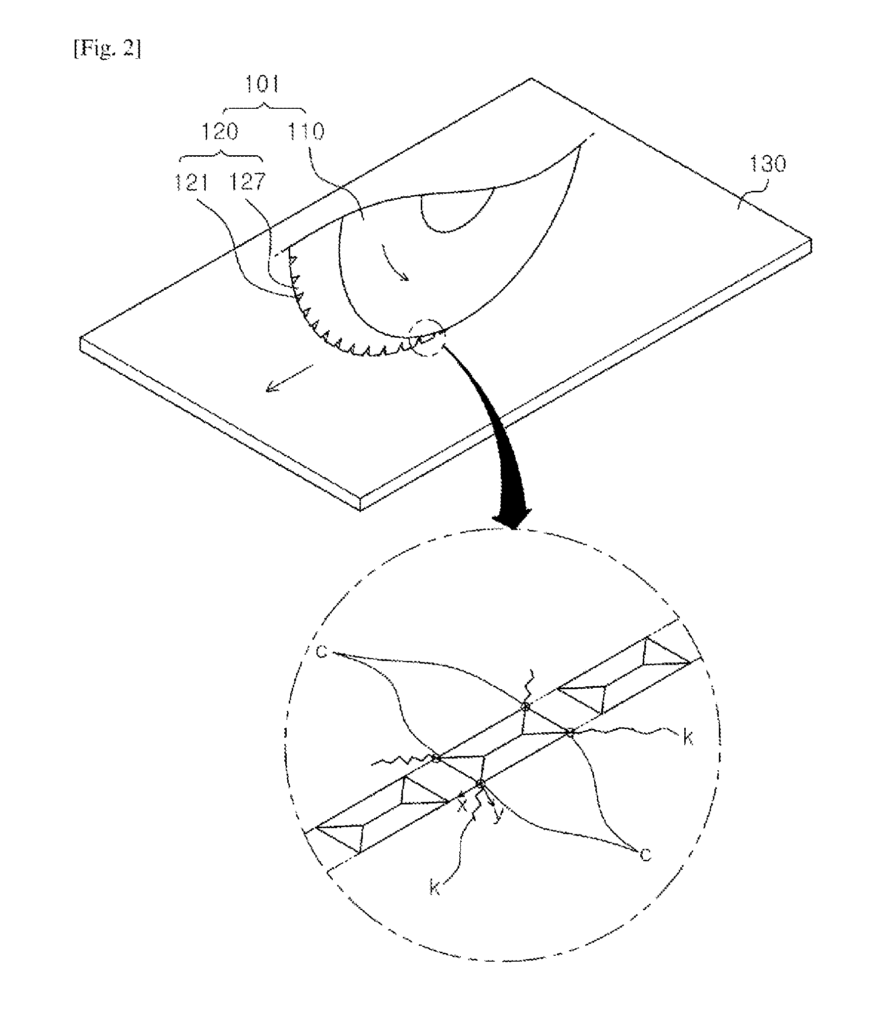
Furthermore, as stated above, because the area of a portion of the scribing target on which stress is concentrated is greatly increased in X- and Y-axial directions due to the structure of the recesses of the scribing wheel, relatively large cracks are formed in side surfaces of the flat panel produced through the scribing process.
However, these cause problems of an increase in material consumption and a reduction in productivity because of addition of the side surface grinding process.
If the recesses formed in the cutter part have a V or U shape in which they are recessed from only the cutting edge of the wheel, large cracks are caused around the vertexes of the cutting blade teeth.
However, because the width of each recess ranges from 20 μm to 40 μm and the depth thereof ranges from 6 μm to 12 μm, it is difficult to use such a scribing wheel in cutting a thin panel for mobile devices.
However, if the above-mentioned conventional scribing wheels are used to manufacture flat panels for use in display panels for mobile terminals and tablet PCs, the bending strength of products cannot be satisfied because of the above-mentioned problems.
In this case, it is difficult to satisfy the desired bending strength.

Method used


Image

  • Scribing wheel having fine structure recess
  • Scribing wheel having fine structure recess
  • Scribing wheel having fine structure recess

Examples


experimental example 2

[0110]Processes of scribing organic panels of 250 μm using the scribing wheels 1 manufactured according to embodiments 1 and 2 and the scribing wheel according to the comparative example were conducted, and scribing depths depending on working loads were measured. The measurement results are shown in Table 1.

TABLE 1Working loadScribing depthClassification(N)(μm)Scribing wheel 18.0229Scribing wheel 28.5223Scribing wheel of9.5214comparative example

[0111]As shown in Table 1, it can be appreciated that, in terms of the scribing depth, despite being given a lower working load, the scribing wheel 1 or 2 according to the present invention is superior to the scribing wheel of the comparative example. In addition, according to the present invention, it was possible to break the glass panel even with a relatively low working load ranging from 8 N to 8.5 N.

experimental example 3

[0112]The bending strength of the flat panels 40, having a thickness of 500 μm, obtained by the scribing wheels 1 and 2 according to the present invention, and the bending strength of the flat panel 140 obtained by the scribing wheel of the comparative example were measured by a method of FIG. 11. The results are shown in Table 2.

[0113]Conditions of a bending strength test are as follows.

[0114]A)

[0115]Test method: 3-point bending test

[0116]B)

[0117]Loading speed: 12.5 mm / min

[0118]C)

[0119]Sample size: length 30×width 10×thickness 0.5 (mm3)

[0120]D)

[0121]The number of test samples: 100

[0122]E)

[0123]Bending strength calculation formula: σf=3PL / 2Wt2

[0124]{σf: bending strength, P: maximum load when sample is broken, L: distance between sample supports, W: width of sample (10 mm), t: thickness of sample (0.5 mm)}

TABLE 2Working loadBending strengthClassification(N)(Mpa)Scribing wheel 18.0353Scribing wheel 28.5389Scribing wheel of9.5316comparative example

[0125]It can be understood from Table...

experimental example 4

[0128]To compare the lifetime of the scribing wheels 1 and 2 manufactured by embodiments 1 and 2 with that of the scribing wheel of the comparative example, each scribing wheel scribed glass panels having a thickness of 0.5 mm until the scribing distance that the scribing wheel has scribed the glass panels was 1.8 km, and then the bending strength of the glass panels, obtained after the scribing wheel has scribed 0.6 km, 1.2 km and 1.8 km, was measured. The results are shown in FIG. 12.

[0129]As shown in FIG. 12, in the scribing wheel 1 or 2 according to the present invention, the bending strength was maintained almost constant regardless of an increase of the scribing distance, compared to the scribing wheel of the comparative example in which the bending strength was sharply reduced as the scribing distance increased. Therefore, it can be understood that the lifetime of the scribing wheels 1 and 2 according to the present invention is improved compared to the scribing wheel of the ...


PUM

PropertyMeasurementUnit
Lengthaaaaaaaaaa
Lengthaaaaaaaaaa
Angleaaaaaaaaaa

Abstract

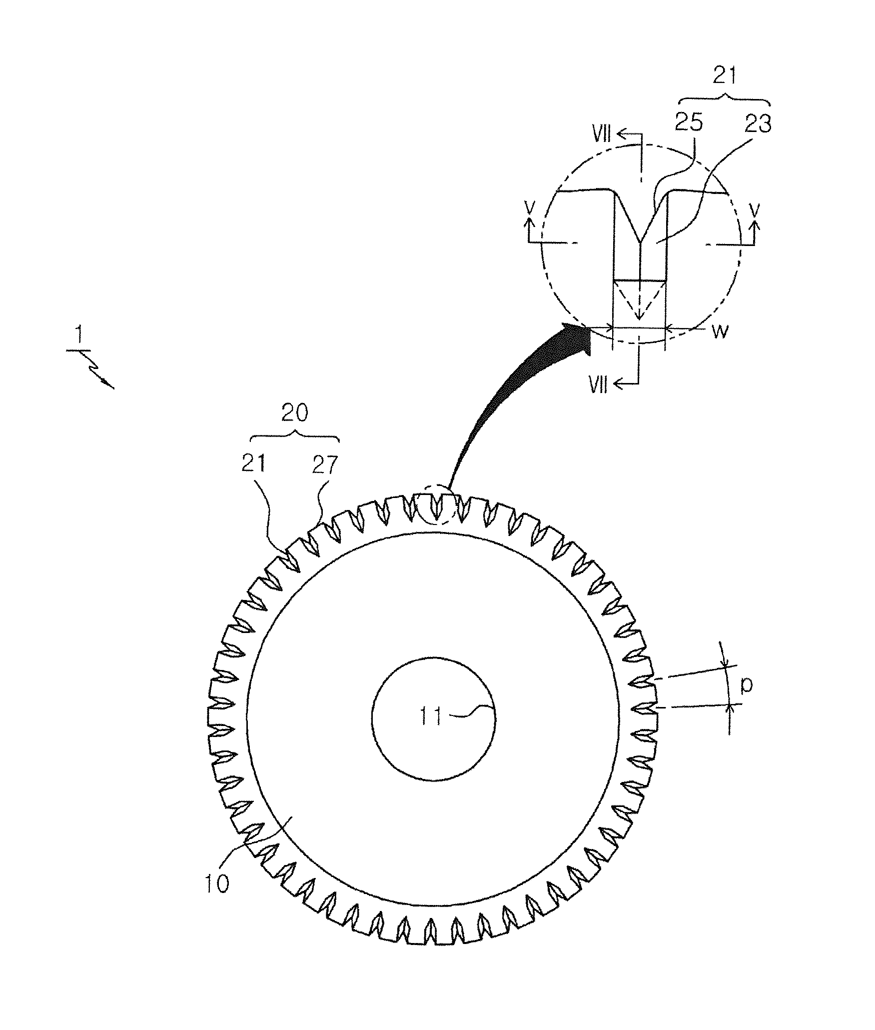
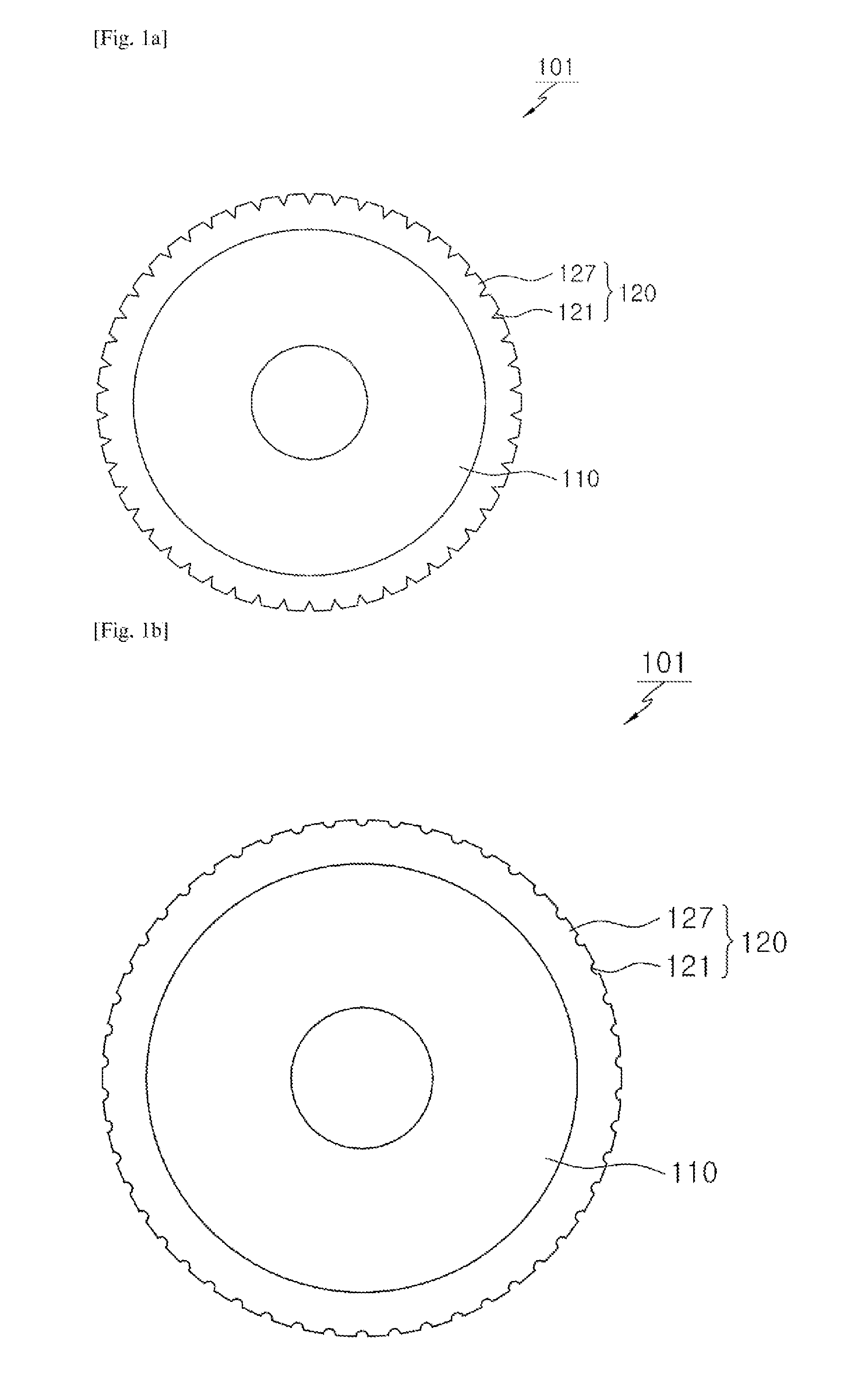
Disclosed herein is a scribing wheel having a predetermined thickness and a disk shape. The scribing wheel includes: a wheel body configured in such a way that at least a peripheral edge portion thereof is gradually reduced in thickness from the center to the radial outside; and a cutter part including recesses and cutting blade teeth which are alternately arranged along the peripheral edge portion. Each recess is formed by a combination of side recess portions formed in opposite side surfaces of the peripheral edge portion of the wheel body and an edge recess portion formed in the peripheral edge of the wheel body.

Description

TECHNICAL FIELD[0001]The present invention relates, in general, to scribing wheels and, more particularly, to a scribing wheel having fine structure recesses which are formed along the peripheral edge of the scribing wheel and have an improved structure to be suitable for cutting, for example, a panel for mobile devices which is generally made of a thin glass panel.BACKGROUND ART[0002]Generally, in producing flat panels such as glass panels for use in an FPD (flat panel display) such as LCDs, touch panels, etc., a process of cutting a large raw material panel into flat panels having a desired size while taking productivity into account is essential. Such a panel cutting process includes a panel scribing process.[0003]The scribing process is typically used in manufacturing a variety of display panels, semiconductor wafers, etc. using flat panels. In detail, the scribing process includes forming a scribing line, corresponding to the size of a flat panel to be produced, on a raw materi...

Claims


Application Information

Patent Timeline
IPC IPC(8): C03B33/10B26D3/08
CPCB26D3/085C03B33/107B26D3/08B26D2001/0053B28D1/225Y10T83/0385Y02P40/57B28D5/00C03B33/033C03B33/10
Inventor JEON, CHANG HOLEE, SUNG HEEKIM, SANG BEOMSHIN, TAEK JUNGLEE, SEH KWANGKIM, IN SUB
Owner NIWA DAIYAMONDO INDS
Learn More