Injection molding apparatus

Inactive Publication Date: 2008-07-24
SAMSUNG ELECTRONICS CO LTD
View PDF6 Cites 3 Cited by
  • Summary
  • Abstract
  • Description
  • Claims
  • Application Information

AI Technical Summary

Benefits of technology

[0008]Accordingly, the present invention has been made to address above-mentioned problems occurring in the related art, and an a

Problems solved by technology

However, because the mold is rapidly heated and then cooled in the molding process, high tensile stress repeatedly acts on corn

Method used


Image

  • Injection molding apparatus
  • Injection molding apparatus
  • Injection molding apparatus

Examples


Embodiment Construction

[0024]Hereinafter, exemplary embodiments of the present invention will be described with reference to the accompanying drawings.

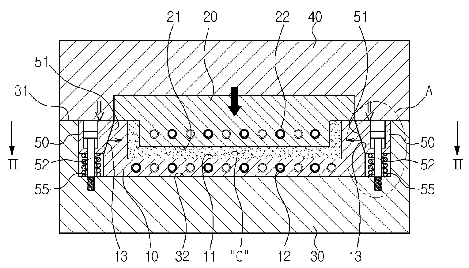
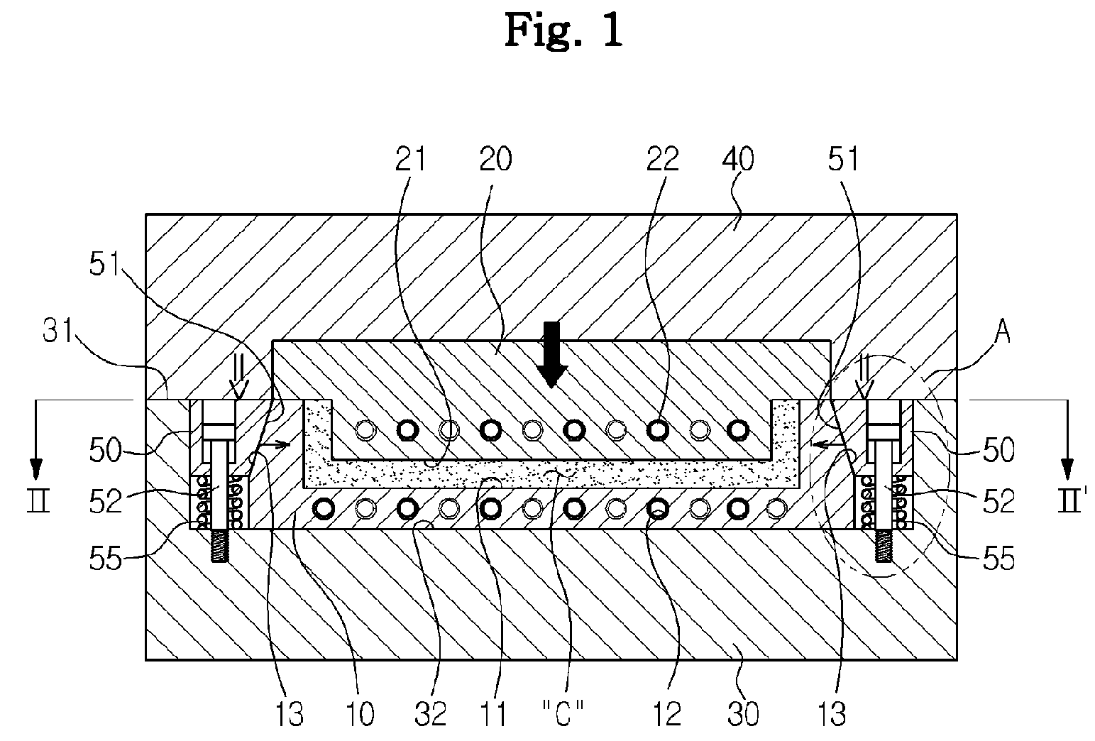
[0025]As illustrated in FIGS. 1 and 4, an injection molding apparatus according to the present invention first and second molds 10 and 20 mating with each other to define a molding cavity C, a stationary member 30 supporting the first mold 10, and a movable member 40 supporting the second mold 20 and moving backwards and forwards together with the second mold 20.

[0026]The stationary member 30 is provided with a mold installation space 32 recessed from a mating face 31 mated with the movable member 40 so as to be able to receive and fix the first mold 10 therein. As illustrated in FIGS. 1 and 2, the first mold 10 is fixed by tapered fixing blocks 33 installed therearound after received in the mold installation space 32. The second mold 20 is fixed to the movable member 40 so as to be able to define the molding cavity C together with the first mold 10, thereb...


PUM

PropertyMeasurementUnit
Pressureaaaaaaaaaa

Abstract

An injection molding apparatus capable of minimizing cracks at the corners of a mold is provided. The injection molding apparatus includes first and second molds that mate with each other to define a molding cavity, a stationary member that supports the first mold, a movable member that supports the second mold and moves backwards and forwards together with the second mold, and a plurality of pressing members installed around the first mold so as to press a periphery of the first mold toward the molding cavity by a pressing force of the movable member when the first mold is mated with the second mold.

Description

CROSS-REFERENCE TO RELATED APPLICATIONS[0001]This application claims priority from Korean Patent Application No. 10-2007-0006606, filed on Jan. 22, 2007, in the Korean Intellectual Property Office, the disclosure of which is incorporated herein by reference.BACKGROUND OF THE INVENTION[0002]1. Field of the Invention[0003]Apparatuses consistent with the present invention relate generally to an injection molding apparatus and, more particularly, to an injection molding apparatus capable of minimizing cracks at the corners of a mold.[0004]2. Description of the Related Art[0005]Recently, the technologies of rapidly heating or cooling a mold in the molding process in order to reduce a molding time and simultaneously produce a good molding have been proposed in the mold field.[0006]As an example, a mold disclosed in Japanese Patent Publication No. 2001-18229 is designed to alternately introduce a heating medium and a cooling medium into a channel in the mold, thereby rapidly heating or coo...

Claims


Application Information

Patent Timeline
IPC IPC(8): B29C45/72
CPCB29C45/2675B29C2045/7393B29C45/64B29C45/56B29C45/04B29C45/26
Inventor HWANG, HAN SUBMIN, SUNG KILEE, SANG HUNLEE, JONG WON
Owner SAMSUNG ELECTRONICS CO LTD
Why Eureka
Try Eureka