Universal serial bus connector

Inactive Publication Date: 2002-06-04
HON HAI PRECISION IND CO LTD
View PDF4 Cites 87 Cited by
  • Summary
  • Abstract
  • Description
  • Claims
  • Application Information

AI Technical Summary

Problems solved by technology

The trend toward miniaturization of electronic devices demands that many such devices have a low profile.
This takes up valuable space on the circuit board 94 that

Method used


Image

  • Universal serial bus connector
  • Universal serial bus connector
  • Universal serial bus connector

Examples


Embodiment Construction

The present invention will be explained in detail by reference to the following description of the preferred embodiments.

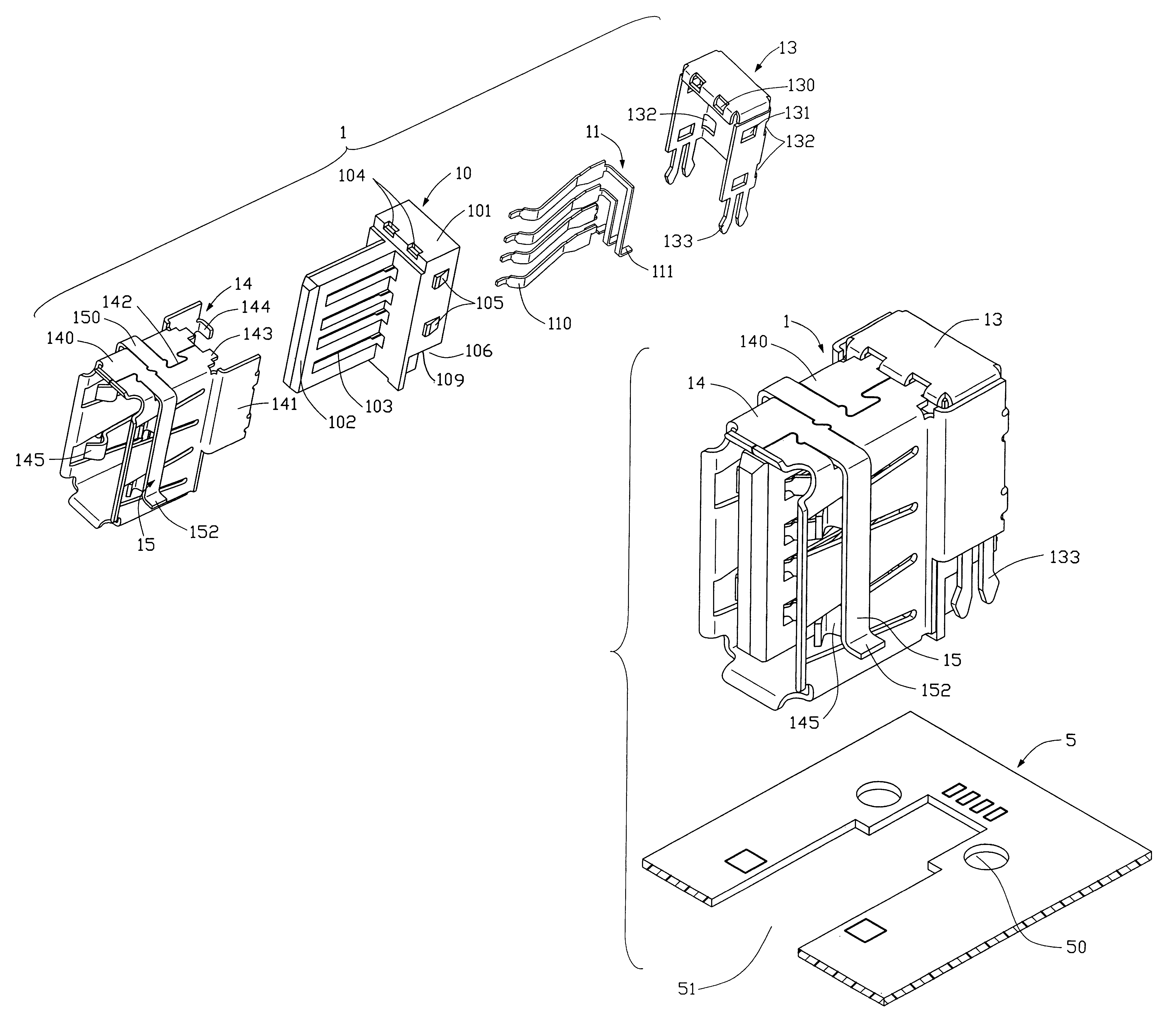
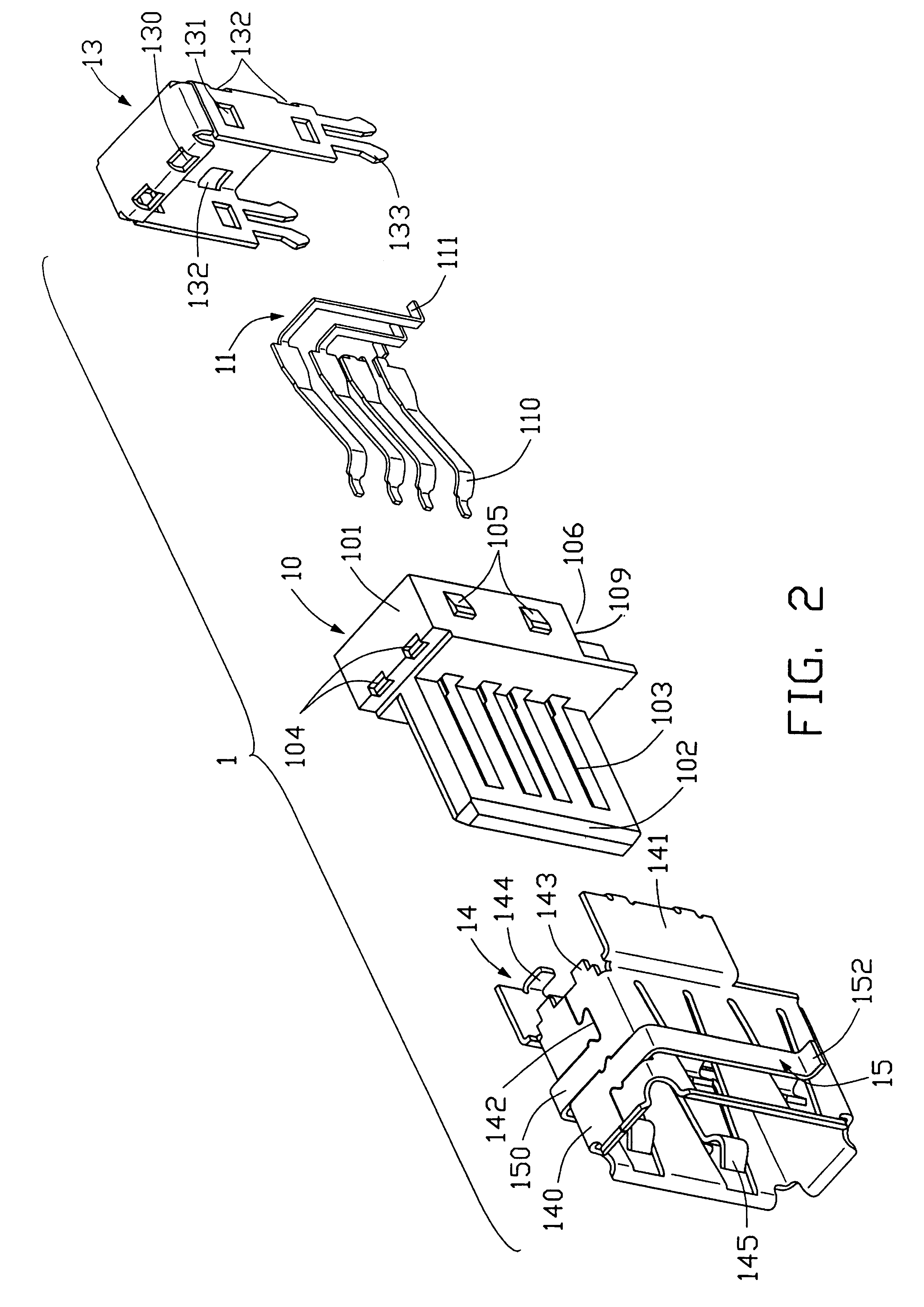
As shown in FIG. 2, an electrical connector 1 in accordance with a preferred embodiment of the present invention comprises an insulative housing 10, a plurality of contacts 11, and first and second conductive shields 13, 14. The housing 10 includes a main body 101, and a tongue board 102 extending forwardly from a front of the main body 101. A plurality of channels 103 is defined in a main face of the tongue board 102 and integrally through the main body 101. A pair of indents 104 is defined at a junction of a front and a top surface of the housing 10. Two blocking tabs 105 are formed on each of opposite side faces of the main body 101. A pair of cutouts 106 (only one shown) is defined in bottommost portions of the opposite side faces of the main body 101 each with a confrontation surface 109 thereon, for facilitating engagement of the connector 1 with a printed c...


PUM


Abstract

An electrical connector comprises an insulative housing, a plurality of conductive contacts, and first and a metal shell. The housing includes a main body, and a tongue board extending forwardly from a front of the main body. The shell comprises first and second conductive shields. The first shield includes a pair of two-pronged fixing portions depending from opposite sides of the first shield respectively, for engaging in a circuit board. The second shield includes two arms depending from a top thereof over outer faces of opposite sidewalls thereof. Each arm forms a bent portion at a lower end thereof, for soldering to the circuit board. Each bent portion is located higher than a bottom of the shell. The fixing portions are disposed higher than the bottom of the shell. The connector is thus attached to the circuit board at four points evenly distributed around a periphery of the connector.

Description

1. Field of the InventionThe invention relates to Universal Serial Bus (USB) electrical connectors, and more particularly to low-profile USB connectors that can be stably and reliably mounted on a printed circuit board.2. Description of the Prior ArtThe trend toward miniaturization of electronic devices demands that many such devices have a low profile. Accordingly, electrical connectors in an electronic device should have a low profile above a printed circuit board on which the connectors are mounted. In order to achieve this, a lower portion of such connectors is mounted below the printed circuit board. Examples of such mounting are disclosed in U.S. Pat. No. 4,457,570 and Taiwan Pat. Application No. 87217216. FIG. 1 shows a Universal Serial Bus (USB) connector with locating means, as disclosed in the Taiwan Pat. Application No. 87217216. Two side wings extend from two side walls of a metal shell 901 of a USB connector 9. A through hole 91 is defined in each side wall. When the co...

Claims


Application Information

Patent Timeline
IPC IPC(8): H01R12/26H01R12/00H01R13/648H01R12/50H01R12/70H01R12/72
CPCH01R12/7023H01R12/707H01R12/7047H01R23/6873H01R12/727H01R13/658
Inventor CHEN, QIANGSHI, GUANGXING
Owner HON HAI PRECISION IND CO LTD
Why Eureka
Try Eureka