Keyswitch for keyboard

Inactive Publication Date: 2002-06-04
BROTHER KOGYO KK
View PDF12 Cites 15 Cited by
  • Summary
  • Abstract
  • Description
  • Claims
  • Application Information

AI Technical Summary

Problems solved by technology

Therefore, overall surface area of the keyboard base must be fairly large; which

Method used


Image

  • Keyswitch for keyboard
  • Keyswitch for keyboard
  • Keyswitch for keyboard

Examples


Example

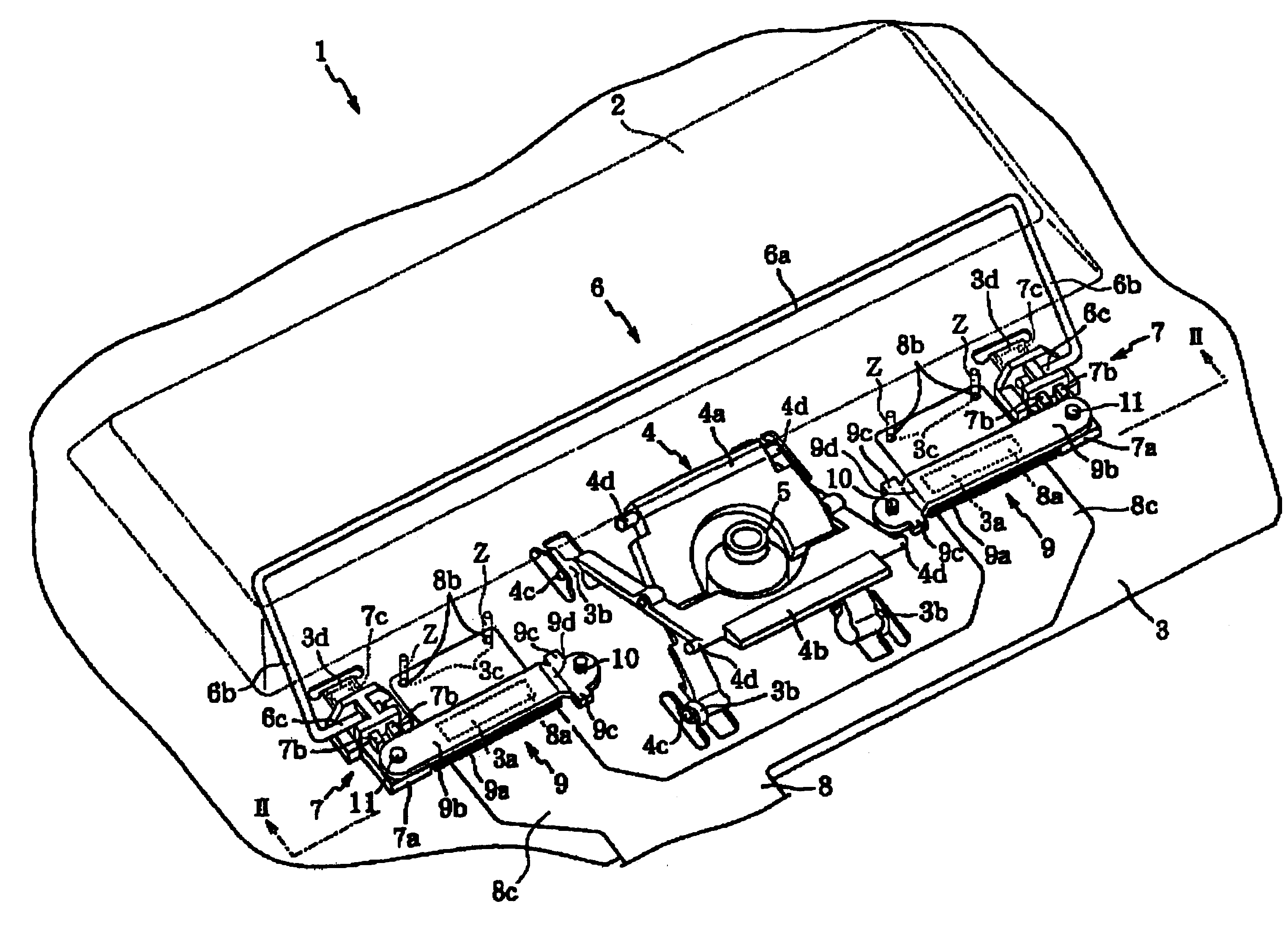
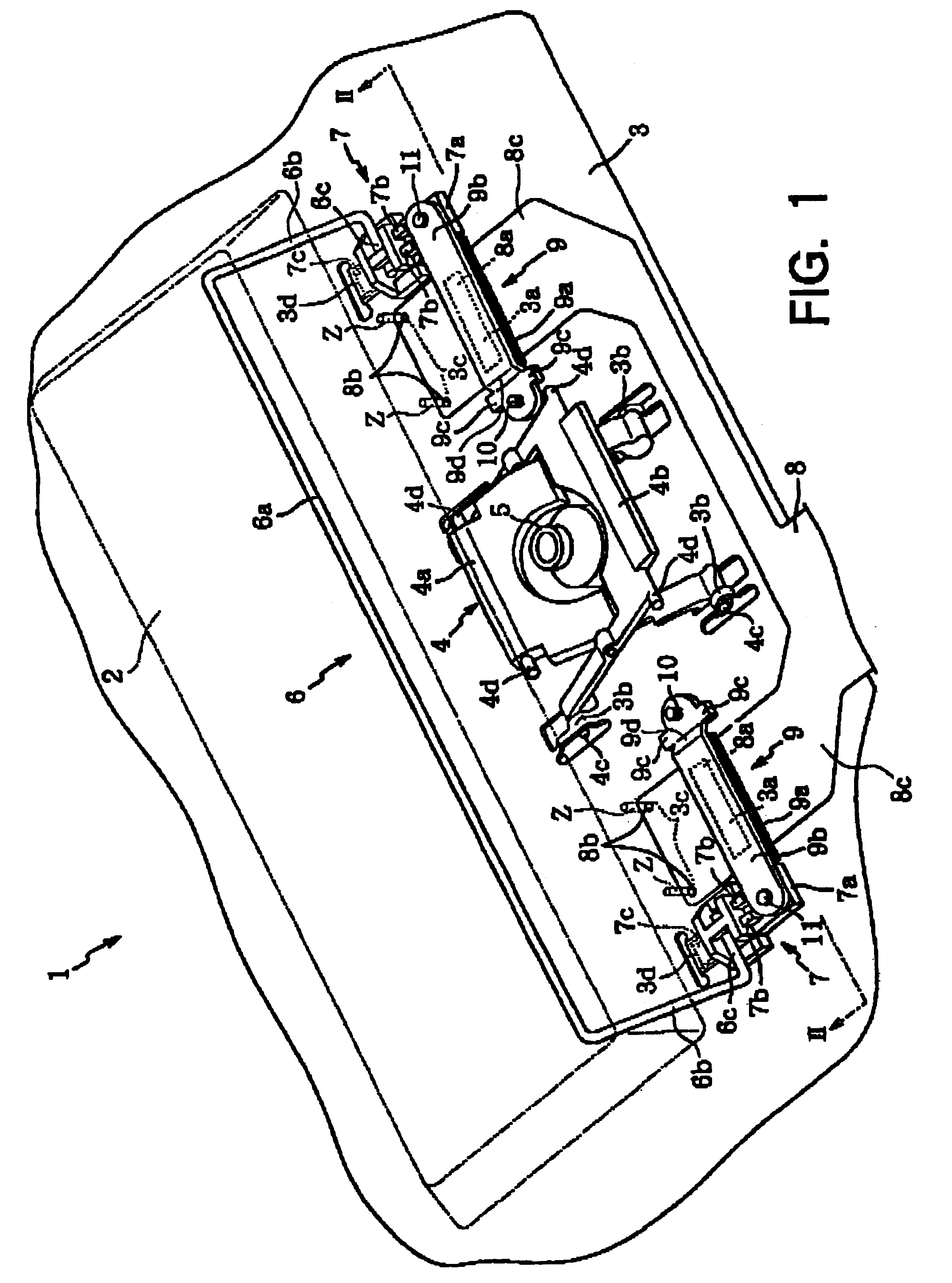
To achieve these objective, a keyswitch according to the present invention includes a keyboard base, an elongated keytop, a guide support member, a flexible circuit base, and a pressing member.

The keyboard base is printed with circuitry. The elongated keytop is disposed above the keyboard base and is longer in a lengthwise direction than in a widthwise direction. The guide support member is disposed below the keytop and guides vertical movement of the keytop.

The flexible circuit base is disposed adjacent, in the lengthwise direction, to the guide support member. The flexible circuit base is electrically connected to the circuitry of the keyboard base to transmit signals from the circuitry on the keyboard base to other circuitry.

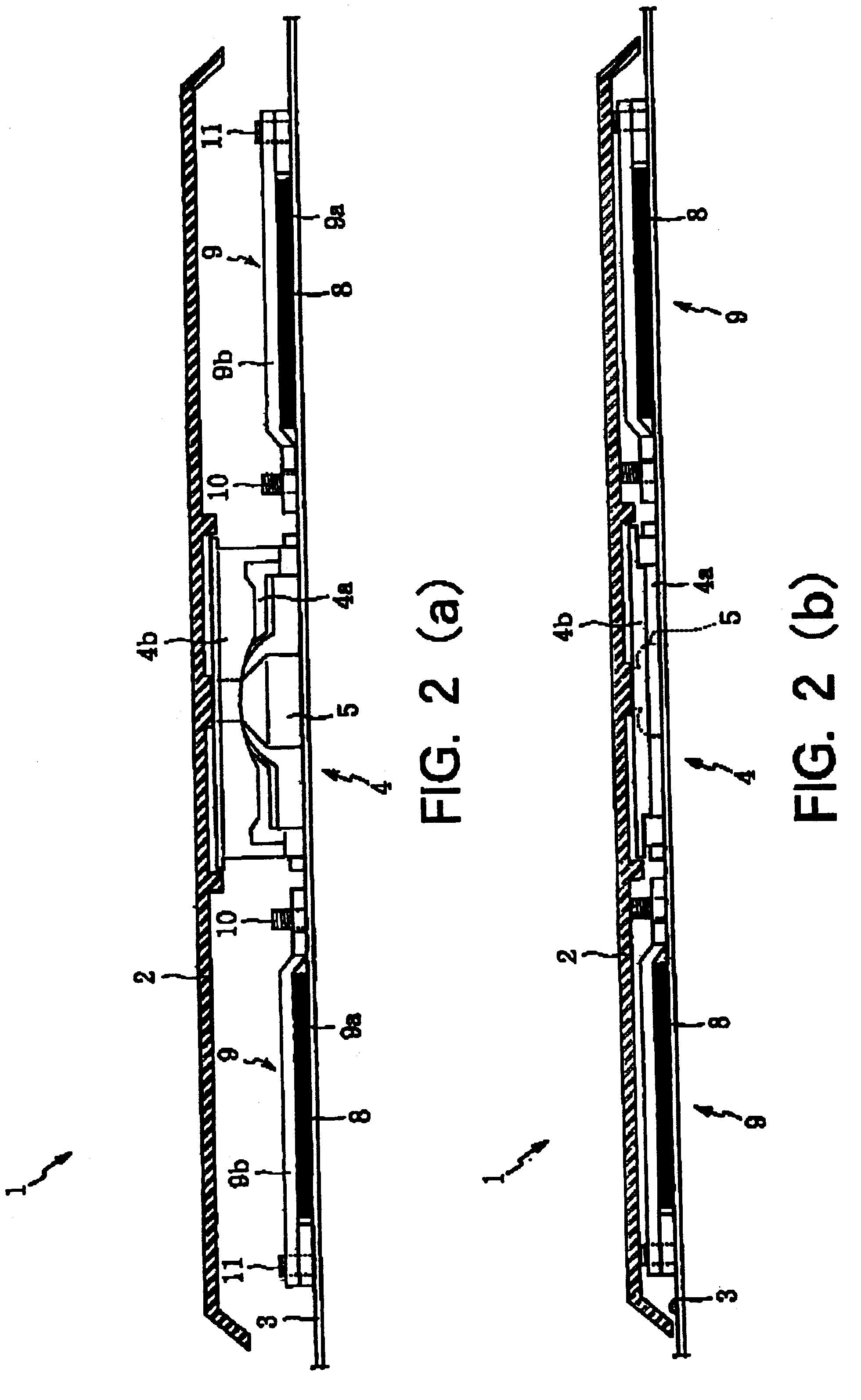
The pressing member is disposed adjacent, in the lengthwise direction, to the guide support member at a position directly below the key top and presses the flexible circuit base towards the keyboard base.

Because the pressing member is disposed directly below ...


PUM


Abstract

A keyswitch includes a keyboard base 3, a guide support member 4 disposed on the keyboard base 3, a flexible circuit board 8 disposed on both sides of the guide support member 4 on the keyboard base 3, an elongated key top 2, and a pressing member 9 for pressing the flexible circuit board 8 toward the keyboard base 3. The pressing member 9 is disposed on both sides of the guide support member 4 directly beneath the elongated key top 2 near lengthwise ends of the elongated key top 2. When the elongated key top 2 is pressed down the guide support member 4 and the pressing member 9 are housed within the elongated key top 2.

Description

1. Field of the InventionThe present invention relates to a keyswitch, a keyboard including the keyswitch, and an electronic appliance including the keyboard, and particularly to a keyswitch capable of securing a sufficient keystroke while reducing overall surface area of a keyboard base.2. Description of the Related ArtA conventional keyboard has a keyboard base and a flexible circuit board. The keyboard base is for supporting keyswitches, including an elongated space key. The flexible circuit board is for transmitting electric signals from the keyswitches to other circuitry, for example in a personal computer. The keyboard base is printed with a contact point for each keyswitch and pull-out contacts for the flexible circuit board. Normally, the pull-out contacts are disposed at a position separate from the keyswitches.Japanese Patent Application Publication No. HEI-7-283504 discloses locating pull-out contacts for the flexible circuit board at the position of the space key. The sp...

Claims


Application Information

Patent Timeline
IPC IPC(8): H01H3/02H01H3/12H01H13/14
CPCH01H3/122
Inventor OKADA, HIROAKI
Owner BROTHER KOGYO KK
Why Eureka
Try Eureka