Magnetic head producing method

a production method and magnetic head technology, applied in the field of magnetic head, can solve the problems of low efficiency of magnetic field (which is necessary for information recording), unfavorable material processing, and inability to produce magnetic head surface,

Inactive Publication Date: 2002-06-11
ALPS ALPINE CO LTD
View PDF12 Cites 6 Cited by
  • Summary
  • Abstract
  • Description
  • Claims
  • Application Information

AI Technical Summary

Benefits of technology

Further, with the use of the present invention, since it is allowed to form a small thickness of .alpha. phase which does not have any direct effect on the magnetic recording characteristic, and since it is allowed to dispense with a base layer which was otherwise indispensable in a prior art, it is possible to reduce an undesired spacing loss, thereby ensuring a higher recording density.

Problems solved by technology

The above problem is caused due to a crystal structure forming the surfaces of the core layers of the thin film element 3.
Moreover, if the surface structures of the lower core layer 13 and the upper core layer 15 involve .alpha. phase having a considerable thickness, an undesired spacing loss will become large, resulting in a low efficiency of a magnetic field (which is necessary for information recording).
Also, it was found from several experiments that once a carbon film is directly formed on the surface of .gamma. phase, an undesired phenomenon such as separation (peeling) will occur.
Thus, the carbon film 10 is not easy to separate (peel) from the core layers.

Method used


Image

  • Magnetic head producing method
  • Magnetic head producing method
  • Magnetic head producing method

Examples


Embodiment Construction

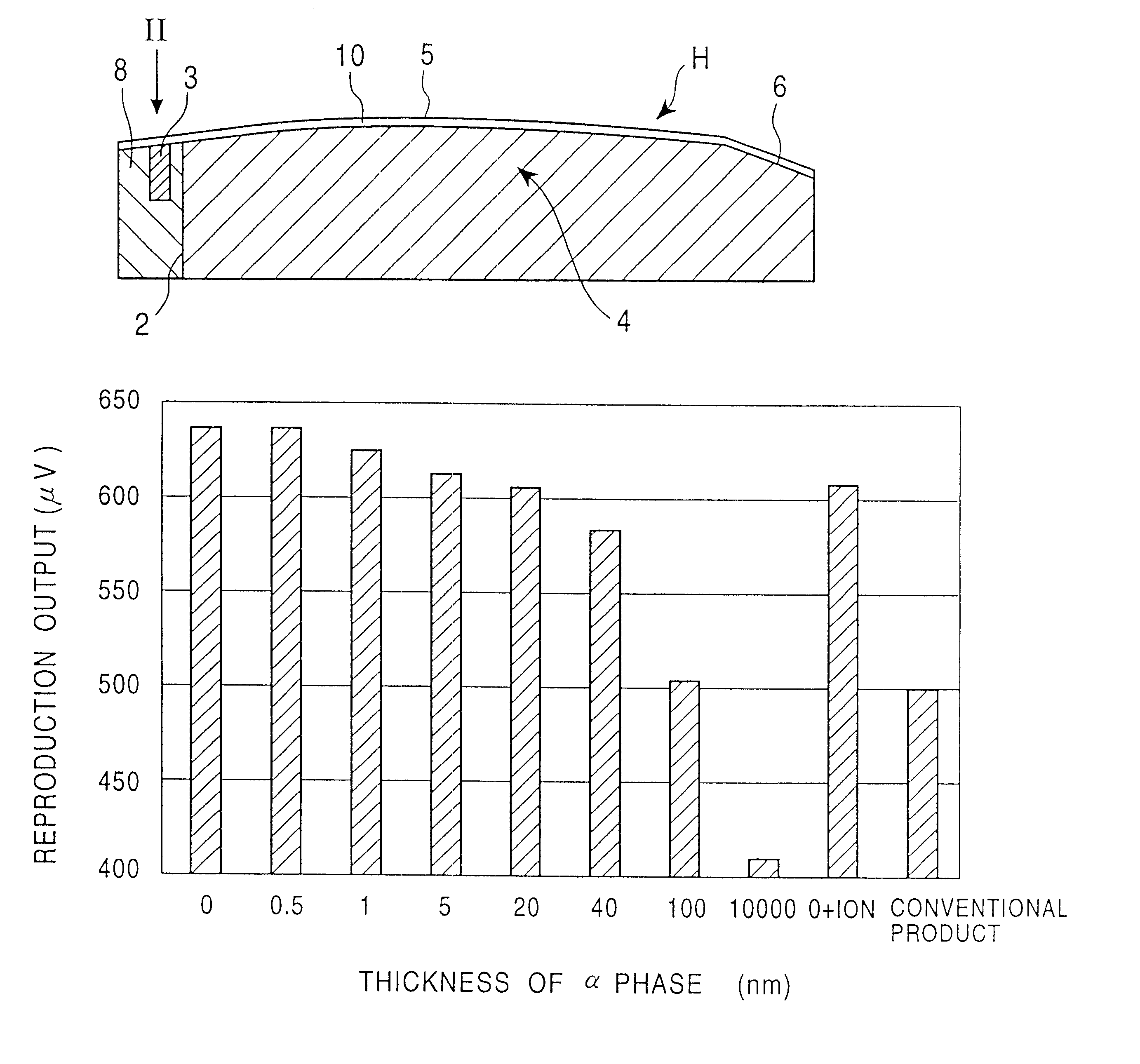
The thickness of the .alpha. phase forming the surface structures of the core layers 13 and 15 was made different for several cases, the MR head (read-out head) was used to reproduce the information previously recorded on the hard disc by means of the inductive head (write-in head). Then, a relationship between the thickness of an .alpha. phase and reproduction output was investigated and test results are indicated in FIG. 3.

In this test, the thickness of a carbon film 10 in contact with an .alpha. phase is 5.5 nm for all the cases involved in the test, regardless of a fact that phase thickness is different from one .alpha. phase to another. In FIG. 3, an expression "0+ion" on the horizontal axis means a condition where an .alpha. phase is completely removed and carbon ions are bombarded into a phase .gamma., finally a carbon film 10 is formed thereon.

As is understood from a graph shown in FIG. 3, a reproduction output will decrease when the thickness of an .alpha. phase increases.

I...


PUM

PropertyMeasurementUnit
thicknessaaaaaaaaaa
thicknessaaaaaaaaaa
thicknessaaaaaaaaaa

Abstract

An improved magnetic head includes a slider and a thin film element, the later of which is provided on a trailing side of the slider. The slider has core layers. The surfaces of the core layers are abraded so that the thickness of an alpha phase constituting the, surface structures of the core layers may be reduced to a very small value. In this way, even if a carbon film is directly formed on the core layers, it is still possible to ensure a desired diffusion between the carbon film and the alpha phase, which effectively prevents the carbon film from separation (peeling) and avoiding the formation of any spot on the carbon film.

Description

1. Field of the InventionThe present invention relates to a magnetic head having a slider which is adapted to be mounted on a device such as a hard disc device. In particular, this invention relates to a magnetic head capable of reducing a spacing loss by directly forming a carbon film on the surfaces of core layers of a thin film element provided on the above slider. The present invention also relates to a method for manufacturing such an improved magnetic head.2. Description of the Related ArtFIG. 4 is a cross sectional view indicating a conventional magnetic head adapted to be mounted on a hard disc device, with its surface facing upward (facing a recording medium).Referring to FIG. 4, the magnetic head involves an upstream side A and a downstream side B (when viewed along the disc's moving direction), with the upstream side A referred to as leading side and the downstream side as trailing side.In FIG. 4, a reference numeral 1 represents a slider formed by a ceramic material. On ...

Claims


Application Information

Patent Timeline
Patent Type & Authority Patents(United States)
IPC IPC(8): G11B21/21G11B5/60G11B5/48G11B5/31G11B5/255
CPCG11B5/4826G11B21/21G11B5/60Y10T29/49052
Inventor SAITO, HIDETOSHIOTSUKA, TOMOOIIZUKA, MASAHIRO
Owner ALPS ALPINE CO LTD
Why Eureka
Try Eureka