Check valve arrangement for a diagnostic test point

Inactive Publication Date: 2002-06-25
SCHROEDER INDS L L C
View PDF25 Cites 4 Cited by
  • Summary
  • Abstract
  • Description
  • Claims
  • Application Information

AI Technical Summary

Benefits of technology

Advantageously this aspect of the present invention enables a smaller diameter valve body to be used in conjunction with a conventional pressure testing probe. This in turn leads to a reduction in the force required to open the check valve in order to take a pressure reading and thereby enables the check valve to be opened at higher pressures without the need for tools.

Problems solved by technology

Problems arose with the usage of such ball valves as leakage or weeping is difficult to control in such systems, particularly when gaseous fluids are being used.
One problem associated with known poppet type check valves of test points is that it is typical for the seal carried on the movable valve body to be pinched between the valve body and the bore of the valve housing during closing of the check valve under pressure.
In particular, the seal may be distorted from its desired shape under the action of the fluid pressure and is often forced into the gap between the valve body and the valve housing during the closing of the check valve, thereby pinching the seal.
This effect during closing of the check valve leads to damage of the seal and subsequent premature failure.
A further problem with known test points for pressurised fluid systems is that there is a limitation upon the fluid pressure at which the test point can be opened by hand in order to take a pressure reading.
Any change to this thread would cause significant problems as existing tools and probe attachment apparatus would no longer fit to the new test points.
As such it is generally not feasible to overcome this problem by reducing the pitch of the thread.
Such a limitation is particularly undesirable.

Method used


Image

  • Check valve arrangement for a diagnostic test point
  • Check valve arrangement for a diagnostic test point
  • Check valve arrangement for a diagnostic test point

Examples


Embodiment Construction

The present invention will be better understood and appreciated from the following discussion of the features of a preferred embodiment.

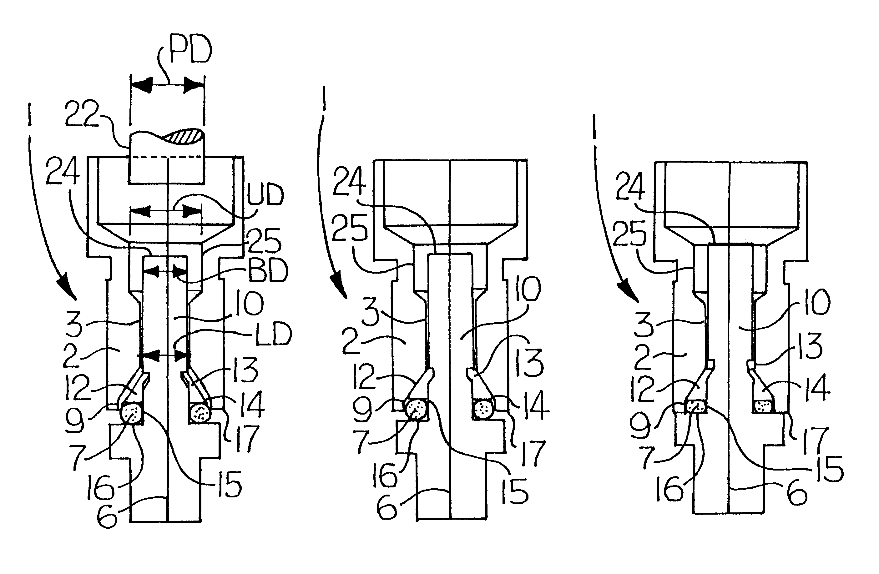
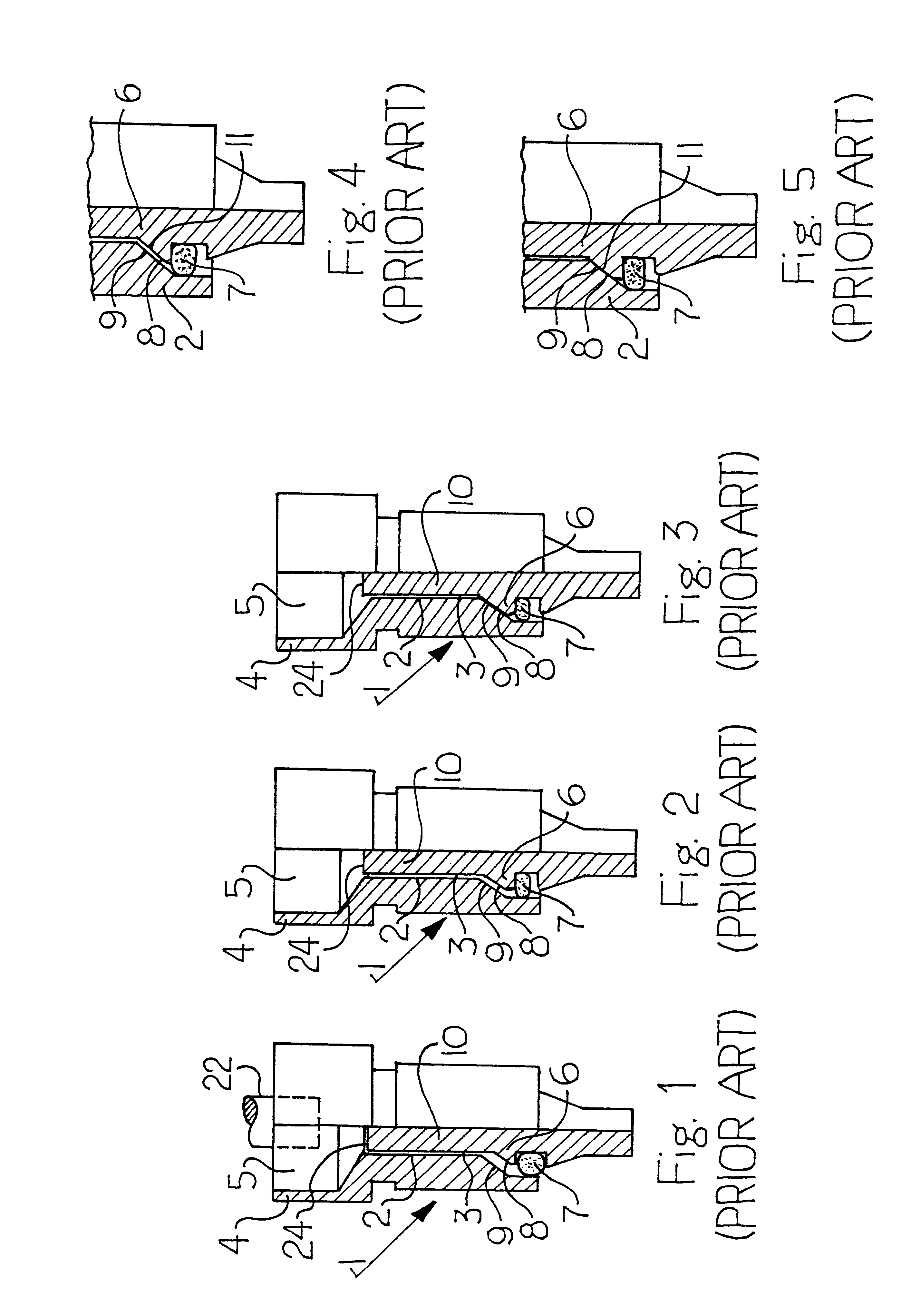
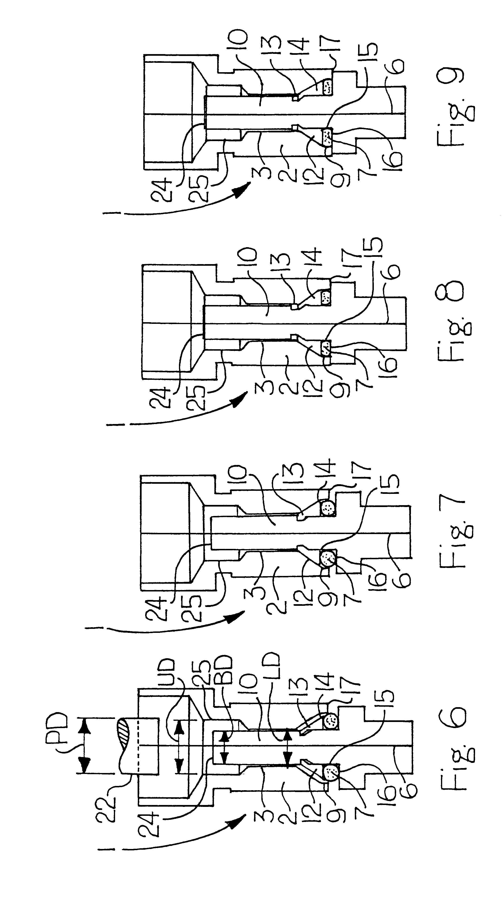
Referring to the sequence of FIGS. 1 to 5, a contemporary design of test point check valve is illustrated. The check valve 1 comprises a housing 2 with a longitudinal bore 3 which passes therethrough. The housing 2 may form a liner or sleeve adapted to be located inside a further, outer housing of a fully assembled test point. One end 4 of the check valve includes an opening or mouth 5 adapted to receive a connection of a fluid pressure measuring device such as that which is shown in FIG. 12.

The test point check valve further includes a valve body 6 located and slidable within the bore 3 of the housing 2. The valve body carries a seal 7, typically an O-ring seal, for sealing of the bore of the check valve. The valve body 6 includes a tapered seating surface 8 which seats upon a correspondingly tapered wall 9 of the bore when the check valve is close...


PUM


Abstract

The invention provides a check valve for a test point for taking pressure measurements or fluid samples in a pressurized fluid system, said check valve including a housing having a bore and a movable valve body located in said bore, one end of said housing adapted to receive a pressure measuring probe for taking said pressure measurements or fluid samples, said one end of said housing including an upper bore section within which, in use, said pressure measuring probe is located wherein said movable valve body includes an end, located in said upper bore section, of nominal diameter less than the nominal diameter of said upper bore section. The invention further provides a check valve for a test point for taking pressure measurements or fluid samples in a pressurized fluid system, said check valve including a housing with a bore passing therethrough, a movable body located in said bore for providing opening and closing of said check valve, and a seal located on said movable valve body for providing sealing between said valve body and said bore wherein said check valve includes a collar means located or said movable valve body to support and expand sad seal. The invention also provides a test point including respective check valves.

Description

FIELD OF THE INVENTIONThe present invention relates to a valve arrangement, and in particular to a check valve arrangement for a test point for taking pressure measurements or fluid samples in pressurised fluid systems, including gaseous systems.BACKGROUND TO THE INVENTIONTest points are used to provide testing or measuring connections for pressurised fluid lines of hydraulic or gas systems. Typically a test point is incorporated into a fluid line of a hydraulic or gas system to provide a means by which a pressure measuring device can be connected to the system in order to measure fluid pressure within the system. The test points are also used for obtaining samples of the fluid (gas or liquid) from the system without the requirement of disrupting the system to obtain the sample, and without spillage or other problems which may be encountered. The test point includes a valve arrangement, commonly known as a check valve, to provide for opening and closing of the test point.Known check...

Claims


Application Information

Patent Timeline
IPC IPC(8): F16K31/00F16K31/44F16K51/00F16K15/06F16K15/02
CPCF16K31/44F16K31/00F16K15/06F16K51/00G01L19/0007F16L29/04
Inventor VAN ESSEN, FREDERICK HUBERT
Owner SCHROEDER INDS L L C
Why Eureka
Try Eureka