Backing out of a processor architectural state

a technology of processor architecture and backwards, applied in the field of computers and processors, can solve the problems of encumbering the ordinary retirement cycle, encumbering the decoding stage, and entailing heavy area and time costs, and achieving the effect of enumerating and reducing the number of processors

Inactive Publication Date: 2002-06-25
INTEL CORP
View PDF7 Cites 21 Cited by
  • Summary
  • Abstract
  • Description
  • Claims
  • Application Information

AI Technical Summary

Problems solved by technology

Since the number of internal registers is limited, an absence of available internal registers may occur causing a bottleneck at the decode stage.
Exceptions may be attributable to interrupts and faults generated during execution of instructions.
A system designed to detect and report all exceptions may employ substantial hardware, i.e., a large area on the processor chip, and may encumber the ordinary retirement cycle.
The detection of complex fault events may entail heavy area and time costs, because more verifications are ordinarily employed to check for complex faults.
Complex fault detection may slow the retirement process with verifications for rarely occurring faults.
Implementing either of the above methods may be problematic.
Thus, executing earlier members of the sequence, e.g., .mu.I.sub.1, may be problematic.
Prior art processors may not handle exceptions on instructions produced by decoding a single macro-instruction inefficiently.

Method used


Image

  • Backing out of a processor architectural state
  • Backing out of a processor architectural state
  • Backing out of a processor architectural state

Examples


first embodiment

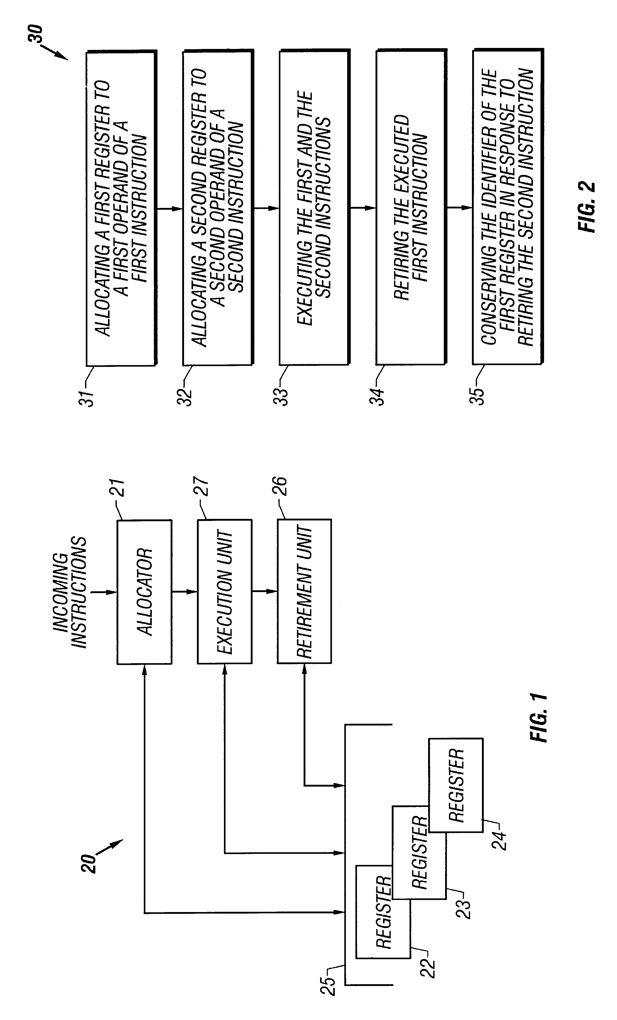
FIG. 1 is a high-level block diagram illustrating a portion of a processor 20 that delays the deallocation of selected registers. In some embodiments, the selected registers include all internal registers. An allocator 21 is a hardware device that assigns registers 22, 23, 24 to a portion of the logical operands of incoming instructions. In some embodiments, the registers 22, 23, 24 belong to a register file 25, i.e., a hardware structure for handling and directing accesses of the plurality of internal registers 22, 23, 24. A retirement unit 26 retires instructions that have been executed by an execution unit 27. The retirement unit 26 deallocates the registers 22, 23:, 24 that were assigned to the executed instructions. Deallocation makes the registers 22, 23, 24 available for assignment to new incoming instructions by the allocator 21. The retirement unit 26 delays the deallocation of a selected portion of the registers 22, 23, 24.

Still referring to FIG. 1, the registers 22, 23, 2...

embodiment 110

FIG. 8 is a flowchart illustrating a method of operating of the processor 60 of FIG. 6. At block 112, the allocator 21 receives a first instruction having a destination logical operand X. At block 114, the allocator 21 assigns a first register to the logical operand X and writes the corresponding first identifier thereof to the speculative assignment position 70 in the RAT 66 for X. Subsequent instructions with the source logical operand X will read the first register. At block 116, the retirement unit 26 retires the executed first instruction and writes the first identifier to the architectural assignment position 71 for X. At block 118, the allocator 21 writes a second identifier, corresponding to a second register, to speculative assignment position 70 for X in response to the second instruction having the address logical operand X. At block 120, the retirement unit 26 writes the first identifier from the architectural assignment position 71 for X to the back-out register 74 in r...


PUM


Abstract

An executed first instruction having a first logical operand as a destination is retired. A register assigned to the first logical operand is identified to back out of an architectural state. The identifying may be performed when an executed second instruction having a second logical operand as a destination is ready to retire or is retired. The register may be assigned to a third logical operand for an instruction to be executed.

Description

1. Field of the InventionThe present invention relates generally to computers and processors, and more specifically, to delaying the deallocation of registers and backing out of architectural states.2. Description of the Related ArtProcessors fetch and execute a sequence of instructions from memory. The instructions ordinarily manipulate data stored in memory or registers. Typically, the processor decodes the instructions into first and second types of micro-instructions adapted to execute on particular types of hardware units. The first type of micro-instruction loads and stores data between the memory and registers, which are typically internal to the processor. The second type of micro-instruction manipulates data stored in the internal registers and writes the results from the manipulations back to the internal registers. Since the number of internal registers is limited, an absence of available internal registers may occur causing a bottleneck at the decode stage. The processor...

Claims


Application Information

Patent Timeline
Patent Type & Authority Patents(United States)
IPC IPC(8): G06F9/38
CPCG06F9/3863
Inventor RAMIREZ, RICARDOMORRISON, MICHAEL J.
Owner INTEL CORP
Why Eureka
Try Eureka