
Quick safety connection for removably joining pipes

a quick safety connection and removable connection technology, applied in the direction of hose connection, pipe-joint, engine seal, etc., can solve the problems of inability to inducing inability to force an untimely displacement of the sleeve, and inability to fully operate the locking means and/or the manoeuvring member

Inactive Publication Date: 2002-07-02
STAUBLI FAVERGES SA
View PDF17 Cites 56 Cited by
  • Summary
  • Abstract
  • Description
  • Claims
  • Application Information

AI Technical Summary

Benefits of technology

Thanks to these means for limiting the movement of the sleeve, the latter cannot be displaced towards a position of release, premature and automatic, of the male connector.
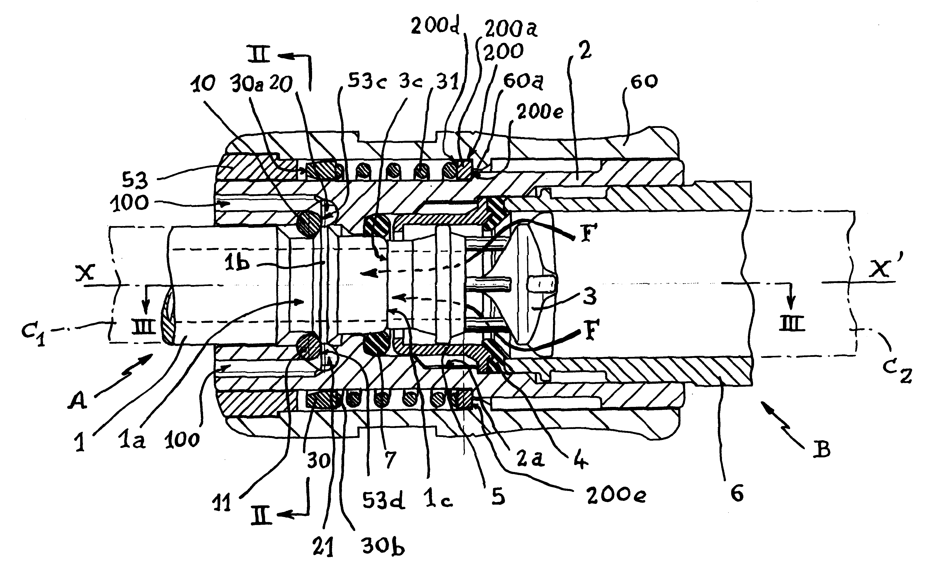
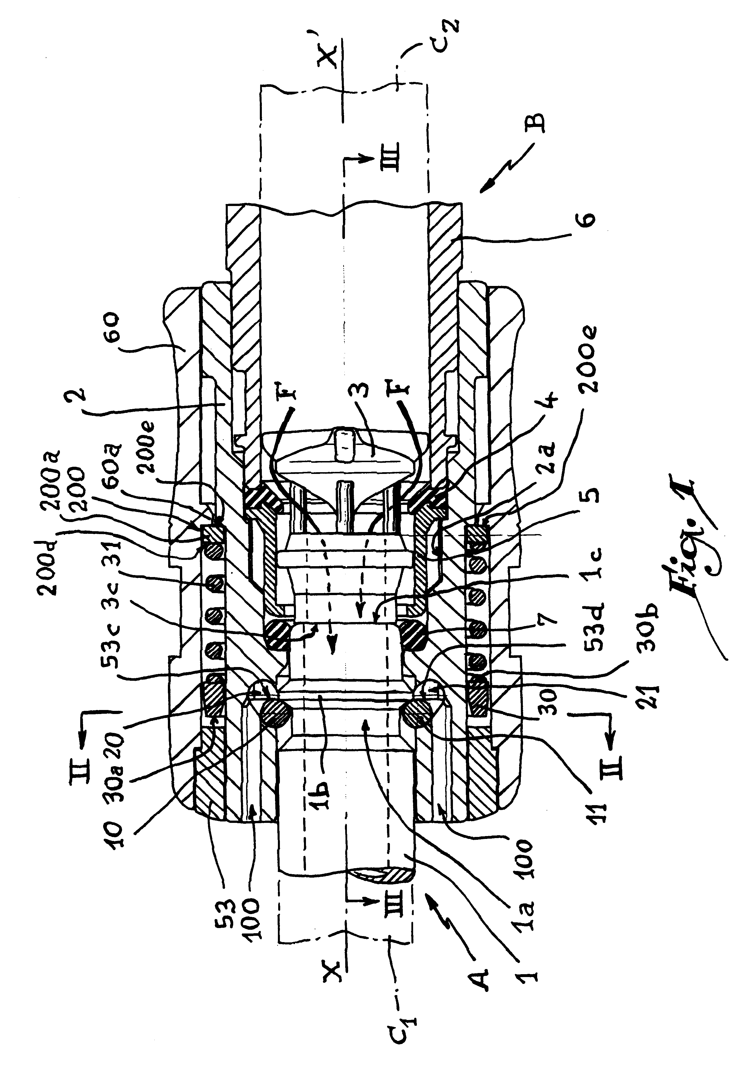
According to a first advantageous embodiment of the invention, the means for limiting the movement of the sleeve comprise venting orifices allowing the flow of the fluid issuing from the downstream pipe, from the inner volume of the sleeve towards the outside of the connection. These vents avoid too great a rise in pressure within the sleeve, particularly in an annular chamber defined around the body of the female element. Such a pressure is therefore not capable of inducing an untimely displacement of the sleeve. The venting orifices advantageously present a total cross-section allowing the flow of the fluid issuing from this downstream pipe without substantial rise in the pressure in the inner volume of the sleeve.
According to a second, particularly advantageous embodiment of the invention, the means for limiting the movement of the sleeve comprise a stop adapted to cooperate with an inner heel of the sleeve, this stop being disposed in the inner volume of the sleeve. Such a stop makes it possible efficiently to limit the movements of the sleeve. According to an advantageous aspect, the stop is formed by a ring disposed around the body of the female element in an annular chamber defined between the body and the sleeve. This ring may be provided to be elastically loaded in the direction of an outer bearing surface of the body and in the direction of the heel of the sleeve. In that case, the means for elastically loading the ring may be formed by means for elastic return of the sleeve into position of engagement of the locking mechanism and / or of the retention member.
According to another advantageous aspect of the invention, the clearance between the body of the female element and the sleeve, downstream of the stop in the direction of flow of the fluid, in the intermediate position of the connector, is greater than the clearance between this stop and the body and / or than the clearance between this stop and this sleeve. This aspect of the invention guarantees that the pressure downstream of the stop is permanently lower than the pressure upstream of this stop, with the result that the stop is permanently subjected to a difference in pressure which tends to apply it towards the bearing surface defined on the body and towards the heel of the sleeve.

Problems solved by technology

Such a displacement may have the consequence of releasing the male connector without the intervention of an operator, which may result in a violent discharge and a potentially dangerous "whiplash".
Such a pressure is therefore not capable of inducing an untimely displacement of the sleeve.
Now, the connectors that may be used with the female elements may have several origins and variable geometries, with the result that the locking means and / or the manoeuvring members are not always fully efficient.

Method used


Image

  • Quick safety connection for removably joining pipes
  • Quick safety connection for removably joining pipes
  • Quick safety connection for removably joining pipes

Examples


Embodiment Construction

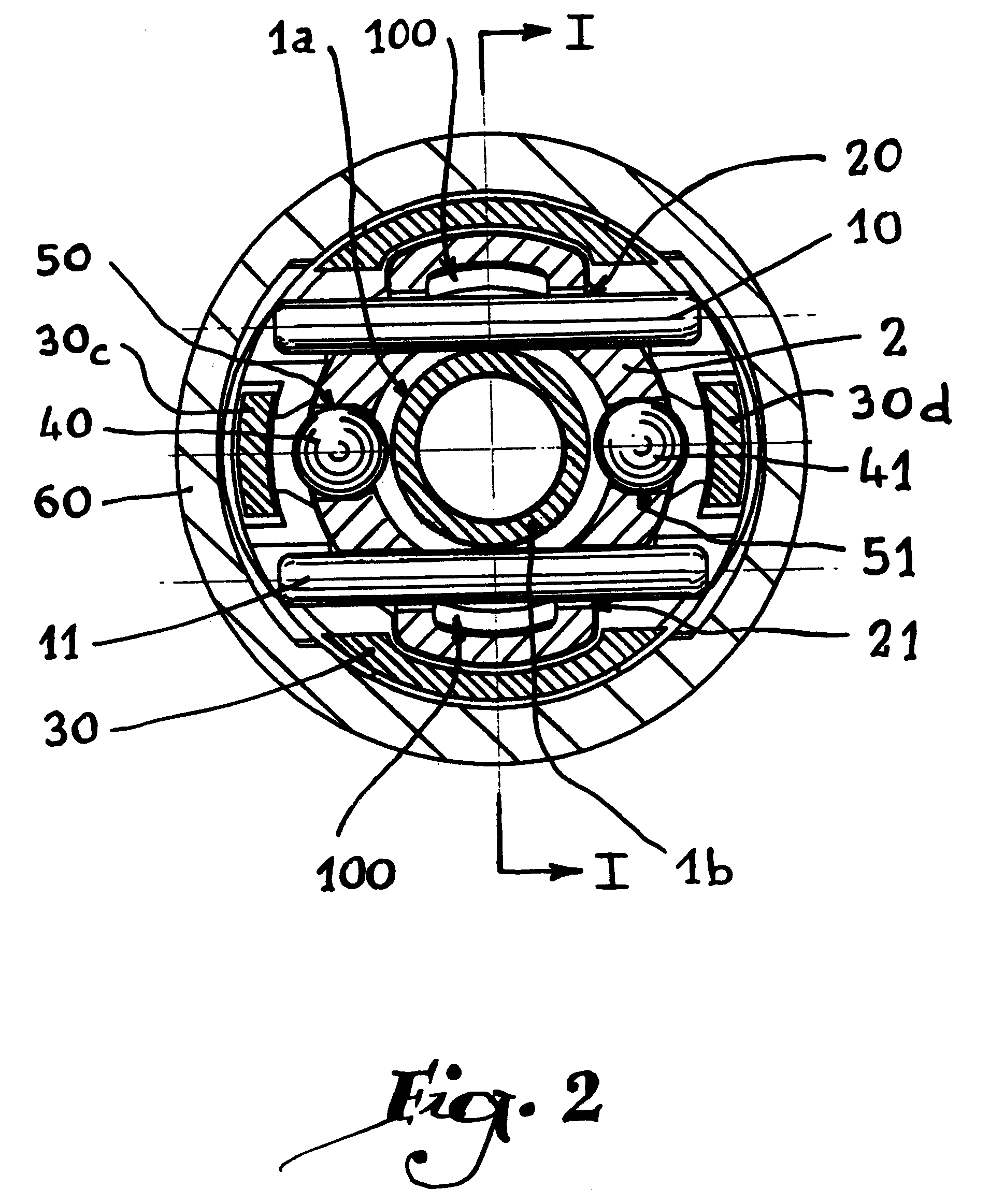
Referring now to the drawings, the quick connection shown in the Figures comprises a male element A and a female element B both provided to be tubular in shape. The male element A is formed by a connector 1 whose rear part (not shown) is fluidically connected to a first pipe C.sub.1. Similarly, the rear part of the female element B is connected to a second pipe C.sub.2 itself connected to a source of compressed air (not shown). The female element B is formed by a tubular body 2 inside which is slidably housed a valve 3 adapted to come into abutment against a seat 4, formed by an elastomer ring immobilized between an inner bush 5 and an outer bush 6 on which the pipe C.sub.2 is connected, bushes 5 and 6 being disposed inside a central bore 2a of the body 2. An O-ring 7 is also provided in this central bore in order to abut against the outer radial surface of the connector 1 when the connection is in coupled position, as shown in FIGS. 1 and 3.

Two needles 10 and 11 are provided to loc...


PUM


Abstract

A quick safety connection for the removable joining of pipes, comprising a male connector and a female element adapted to fit and to be locked inside one another. A controlled locking mechanism is adapted to immobilized the male connector axially in a position of connection, while at least one retention member is provided to immobilize the male connector, after release of the connector by said locking mechanism, in an intermediate position of discharge of the pipe connection. The locking mechanism and retention member are controlled by a sleeve sliding around the female element. Vents and safety stops are provided to limit the movement of the sleeve under the effect of the pressure prevailing due to the discharge of the connection in the intermediate position between the female element and the sleeve.

Description

The present invention relates to a quick safety connection for the removable joining of pipes and, more specifically, to a so-called "double-release" quick connection.DESCRIPTION OF THE RELATED ARTEuropean Patent Application 0 722 063 discloses a double-release quick connection in which two rings are used, provided with elastic claw elements adapted to cooperate successively with an outer groove of a male connector in order to release this connector in two steps, allowing the discharge of the fluid contained in the downstream pipe, which avoids the whiplash movements which might prove dangerous for a user with a single-release connection. Other double-release connections are known for example from U.S. Pat. No. 5,290,009 or DE-A-27 41 512.In these known devices, an outer ring or sleeve is used for controlling, on the one hand, means for locking the male connector in the female element in a position of communication of the pipes, and, on the other hand, members for retaining the conn...

Claims


Application Information

Patent Timeline
IPC IPC(8): F16L37/42F16L37/28F16L37/22F16L37/23F16L37/00
CPCF16L37/22F16L37/23F16L37/42Y10S285/90Y10S285/924F16L37/00
Inventor LACROIX, JEAN-JACQUESCHAMBAUD, ANTOINE
Owner STAUBLI FAVERGES SA
Learn More