Surface light source device of side light type, liquid crystal display and light guide plate

a technology of liquid crystal display and light guide plate, which is applied in the direction of lighting and heating equipment, instruments, transportation and packaging, etc., can solve the problems of reducing the uniformity of light output, generating unsatisfactory regions of low brightness, and difficult to implemen

Inactive Publication Date: 2002-07-02
ENPLAS CORP +1
View PDF11 Cites 43 Cited by
  • Summary
  • Abstract
  • Description
  • Claims
  • Application Information

AI Technical Summary

Benefits of technology

The present invention has been realized after consideration of the above background. Accordingly, it is an object of the present invention to improve a surface light source device of side light type whe

Problems solved by technology

However, the conventional device described above has a tendency whereby an undesirable region of low brightness is generated on the guide plate 2.
This reduces the uniformity of the light output.
These proposed solutions are easily implemented when the back surface of the guide plate is basically a flat surface, but are difficult to implement when a great number of projections are provided on the back surface of the guide plate.
In practice, application of the above proposed sol

Method used


Image

  • Surface light source device of side light type, liquid crystal display and light guide plate
  • Surface light source device of side light type, liquid crystal display and light guide plate
  • Surface light source device of side light type, liquid crystal display and light guide plate

Examples


first embodiment

(1) First Embodiment

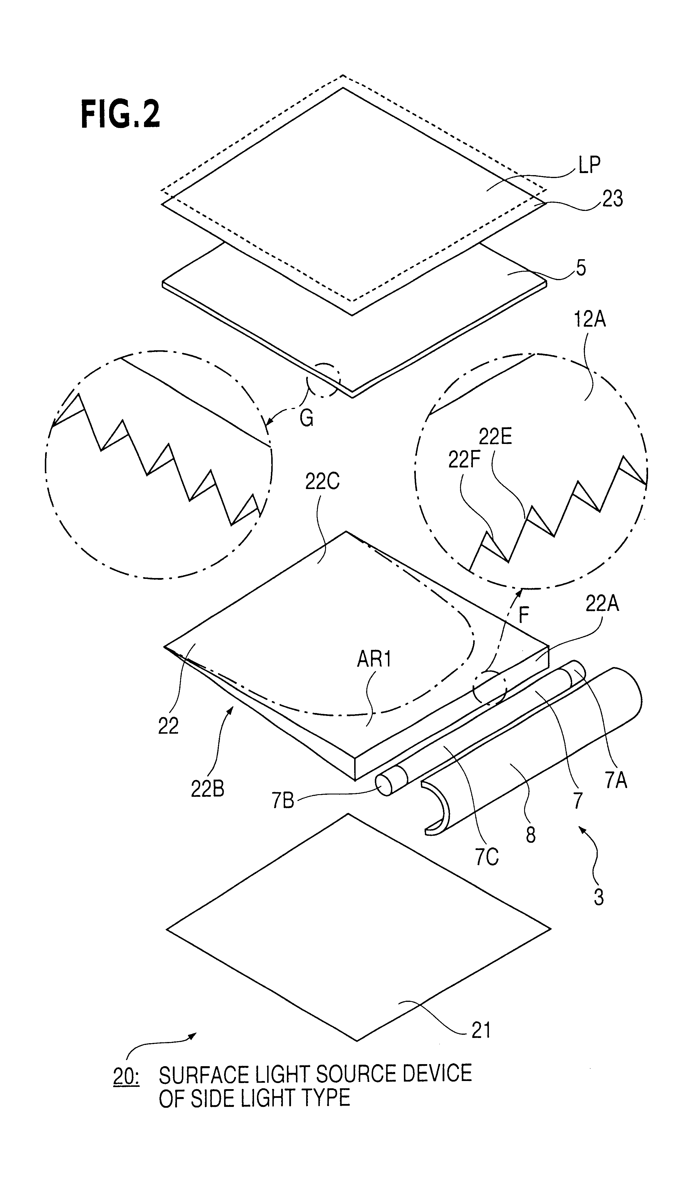
FIG. 2 illustrates a first embodiment in a similar manner to FIG. 24. The surface light source device of side light type 20 is characterized in that a new guide plate 22 is used. The device shown in FIG. 2 differs from that of FIG. 20 in respect of the addition of a light-scattering sheet 23. A constitution of the liquid crystal display is given by further providing a liquid crystal display panel LP, indicated by a broken line. The other elements are the same as shown in FIG. 20. Therefore, the following explanation will concentrate on the characteristics of the present invention, with repeated explanation omitted.

The surface light source device 20 comprises a guide plate 22, a primary light source 3, comprising a wedge-shaped light source element 7 and a reflector 8, a reflection sheet 21, a prism sheet 5 as a light control member, and a light-scattering sheet 23.

The guide plate 22 comprises a scattering guide body which is wedge-shaped in cross-section. The mat...

second embodiment

(2) Second Embodiment

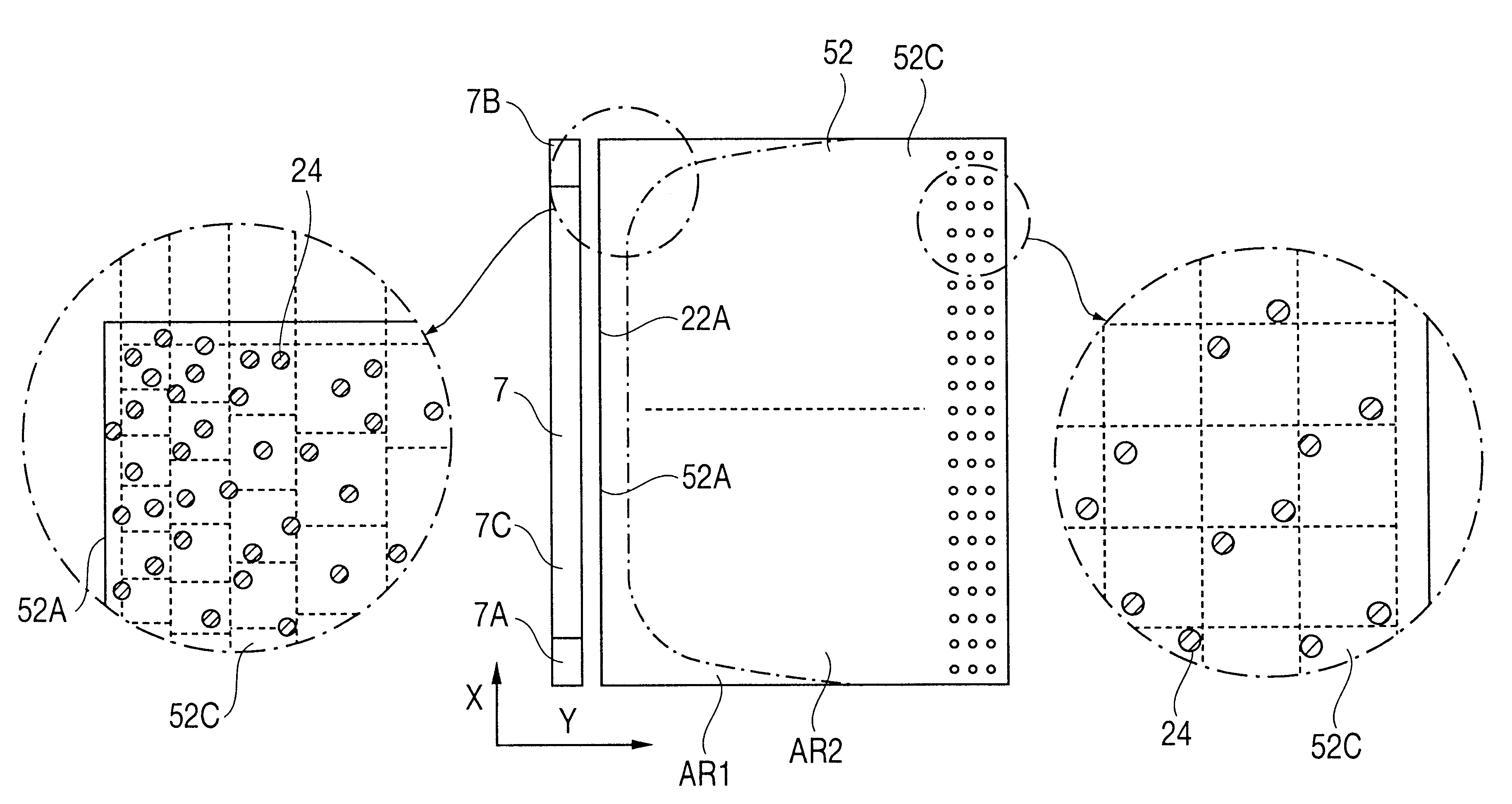
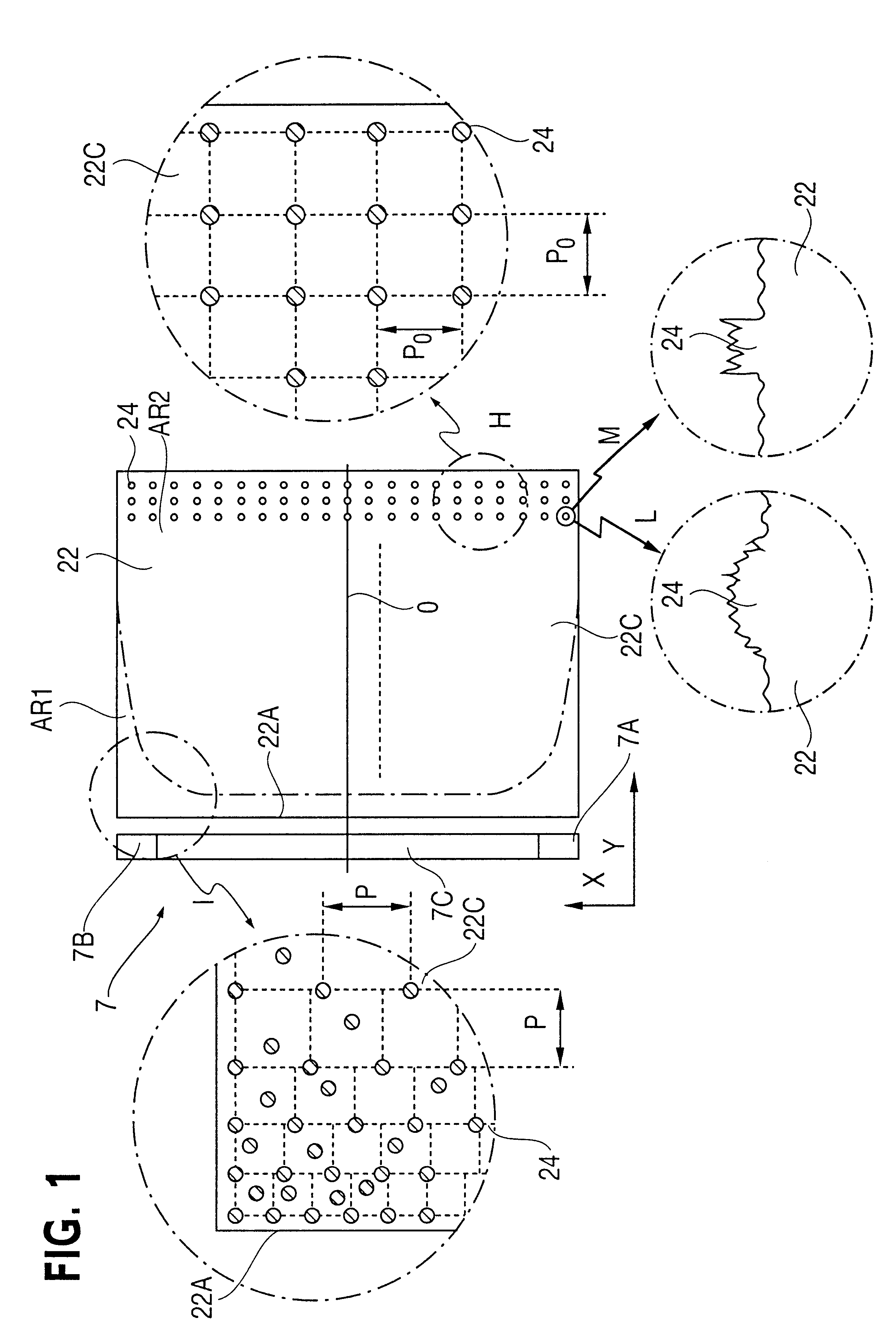
FIG. 10 illustrates, in the same manner as FIG. 1, a scattering pattern arrangement in a scattering pattern guide plate used in a surface light source device of side light type according to a second embodiment. With the exception of the scattering pattern arrangement, structure and functions of this embodiment are identical to first embodiment. Therefore, repetition will be omitted and the following explanation will concentrate on the scattering pattern.

Scattering guide plate 32 is provided with a uniform rough emission surface, which prevents adhesion of the prism sheet 5. Further, the back surface 32B has a great number of projections which run generally perpendicular to the incidence surface 32A. Each projection has a pair of slopes 32E and 32F, and is therefore triangular in cross-section.

As in the first embodiment, the back surface 32B provides a light control surface (prism surface) which gathers illuminating light toward the frontal direction within a sur...

third embodiment

(3) Third Embodiment

FIG. 11 illustrates a third embodiment in the same manner as FIG. 1. This embodiment is characterized in that the surface light source device of side light type 40 uses a new guide plate 42. A liquid crystal panel is not depicted, but one may be provided to the outside of the light-scattering sheet 23 as in the first embodiment. Repeated description of parts which are identical to the first embodiment will be omitted and explanation will concentrate on the characteristic.

The surface light source device 40 comprises a guide plate 42, a primary light source 3, comprising a wedge-shaped light source element 7 and a reflector 8, a reflection sheet 21, a prism sheet 41 as a light control member, and a light-scattering sheet 23.

The prism sheet 41 is provided so that the prism surface is facing the emission surface 42C. This arrangement is selected so that the projections on the prism surface run generally parallel to the incidence surface 42A.

The guide plate 42 compris...


PUM


Abstract

A surface light source device of side light type 40 comprises a guide plate 42, a primary light source 3 comprising a wedge-shaped light source element 7 and a reflector 8, a reflection sheet 21, a prism sheet 41 and a light-scattering sheet 23. The guide plate 42 is wedge-shaped in cross-section and has a back surface 42B and an emission surface 42C. The emission surface 42C is a prism surface. A scattering pattern 24 is provided on the back surface 42B. The scattering pattern 24 comprises a great number of micro-dots, which are sufficiently small that they are hardly visible. Covering rate of the micro-dots is high near an incidence surface 42A, especially at the corners, thereby preventing brightness reduction in a region AR1. Irregularity of the dot arrangement avoids moaré streaks caused in relation to a color filter arrangement of a liquid crystal panel.

Description

1. Field of InventionThe present invention relates to a surface light source device of side light type applied to backlighting, a liquid crystal display and a light guide plate suitable for use therein.2. Related ArtConventionally, a surface light source device of side light type is, for instance, applied to a backlighting arrangement of a liquid crystal display. This arrangement is suitable for making the overall shape of the device thinner.Generally, the surface light source device of side light type uses a wedge-shaped light source, such as a cold cathode tube, as a primary light source which is provided at the side of a light guide plate (plate-like guide body). Illumination light emitted from the primary light source is fed into the guide plate through a side end face thereof. Having been fed inside, the illuminating light propagates through the guide plate, whereby light is output from a major surface of the guide plate toward a liquid crystal display.Known types of guide plat...

Claims


Application Information

Patent Timeline
IPC IPC(8): F21V8/00G02B6/00G02F1/1335G02F1/13357
CPCG02B6/0043G02B6/0061G02B6/0038G02B6/0053G02B6/0055G02F1/133524G02F1/133615
Inventor OHKAWA, SHINGO
Owner ENPLAS CORP
Why Eureka
Try Eureka