
Apparatus and method for recording an optical disc identification code

a technology of optical discs and recording methods, applied in the field of optical disc recording apparatuses, optical disc recording methods, optical discs, etc., can solve the problem that the identification code ed is difficult to be copied

Inactive Publication Date: 2002-07-02
SONY CORP
View PDF10 Cites 26 Cited by
  • Summary
  • Abstract
  • Description
  • Claims
  • Application Information

AI Technical Summary

Benefits of technology

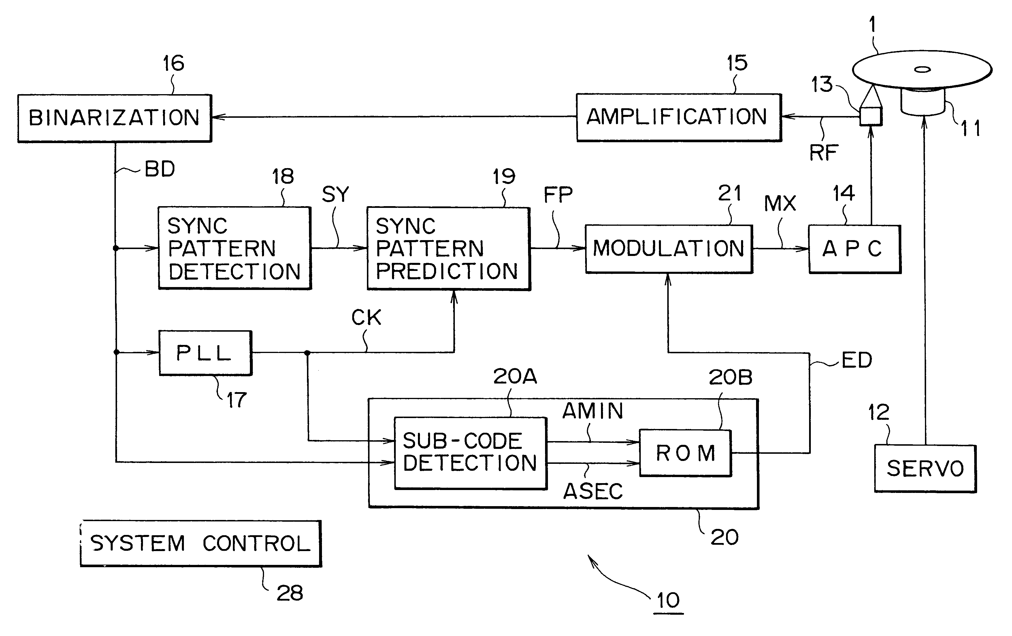
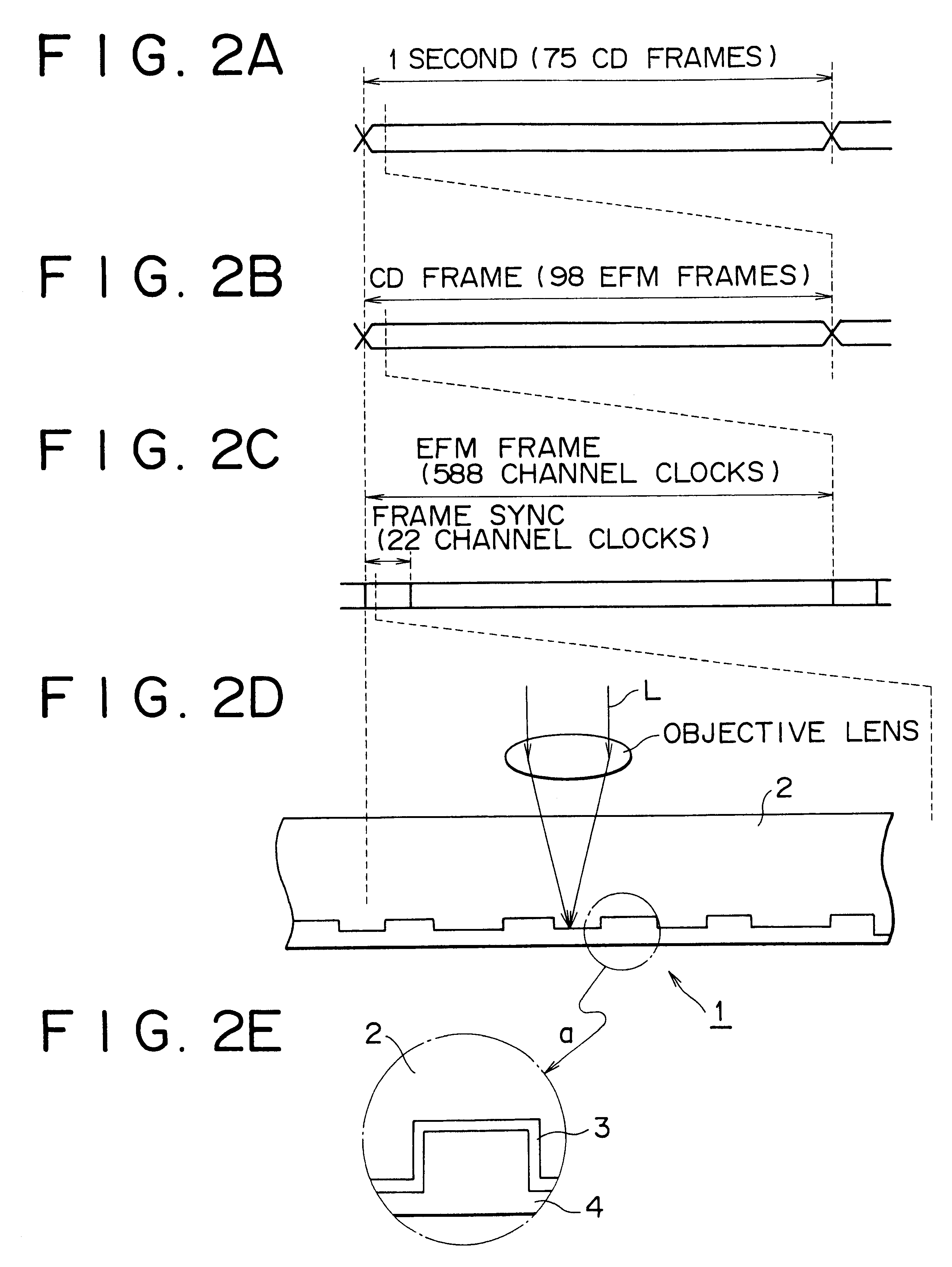
The sub-data recorded in the form of reflectance change of the information recording surface on the disc like recording medium on which the information has been recorded in the form of convex / concave such as pit is not copied by the copying method in which the reflection film is separated and a stamper is made. Thereby, the sub-data string is recorded so that the data of the optical compact disc is protected from being illegally copied. Further, only by minimizing the reflectance change caused from the sub-data recorded as described herein above, the adverse effect of the sub-data on reproduction of the main data is avoided. Further, the sub-data recorded in the form of reflectance change can be detected and decoded as the change of reproduction signal by an optical pickup.
Further, in the present invention, 1 bit sub-data is recorded over a plurality of pits and lands. The reflectance of the information recording surface can be changed locally at the position located a predetermined distance apart from the edge. In the case that the present invention is structured as described herein above, the reflectance can be significantly changed locally without any adverse effect on the timing of the edge. As the result, the sub-data string recorded in the form of significant reflectance change can be reproduced consistently.
Thus in the optical disc as described herein above, the main data string is recorded in the form of repeated pits having the length corresponding to the main data string on the information recording surface and the pit is recorded in the form of physical configurational change of the information recording surface, and the sub-data string is recorded in the form of reflectance change of the information surface, such structure described herein above protects the data in the optical disc from being copied.

Problems solved by technology

However, such a mark is marked so as to be recognized visually, but the mark is not reproduced by an optical pickup of a compact disc player.
Further, the disc identification code ED is made difficult to be copied.

Method used


Image

  • Apparatus and method for recording an optical disc identification code
  • Apparatus and method for recording an optical disc identification code
  • Apparatus and method for recording an optical disc identification code

Examples


second embodiment

(2) Second Embodiment

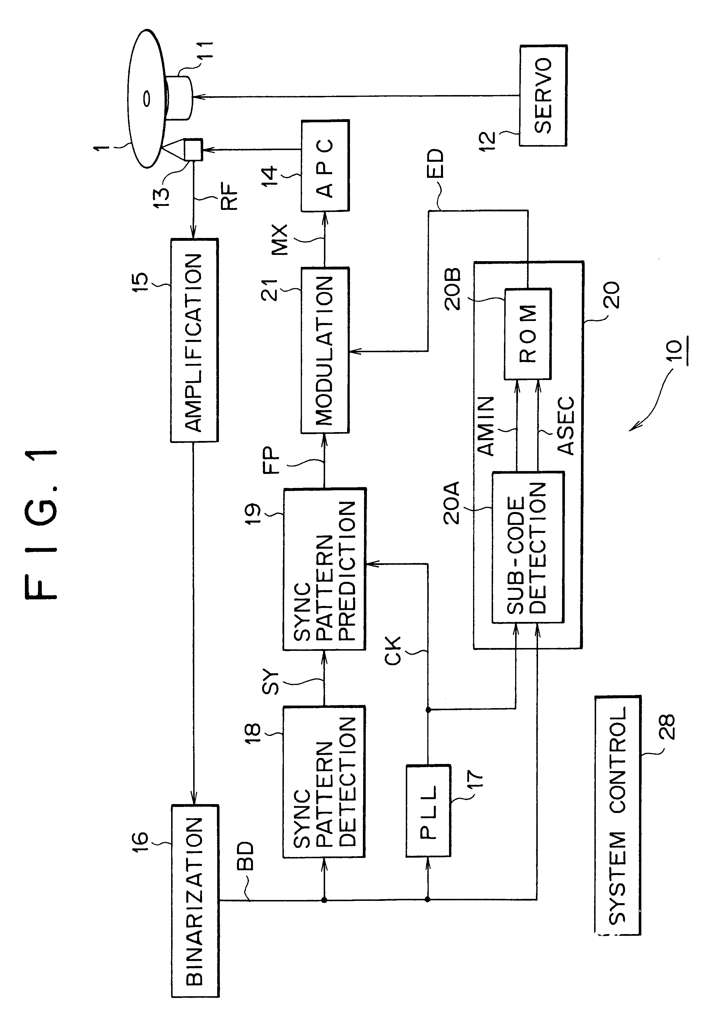
FIG. 7 is a block diagram for illustrating a finishing unit in accordance with the second embodiment of the present invention. The finishing unit 60 detects pits having a cycle equal to or longer than 9T, and records the disc identification code ED on these pits. In the structure shown in FIG. 7, the same components as those of the finishing unit 10 shown in FIG. 1 are given the same corresponding characters, and the repeated description is omitted.

In detail, in the finishing unit 60, the system control circuit 61 comprises a computer for controlling the whole operation of the finishing unit 60, controls the operation of an optical pickup 13 with reference to a sub-code detected from the reproduction signal RF, and traces successively twice the area set on the recording area of the disc identification code ED by means of the optical pickup 13.

At that time, the system control circuit 61 holds the trace signal T1 in logic 0 in the first trace ,on the other hand, s...

third embodiment

(3) Third Embodiment

FIG. 10 is a block diagram for illustrating a compact disc 1 finishing unit in accordance with the third embodiment. This finishing unit 80 performs pit detection processing of the pit having a length equal to or longer than 9T cycles and additional recording processing of the disc identification code simultaneously in parallel. The same components shown in the structure shown in FIG. 10 as those of the above-mentioned finishing unit 60 shown in FIG. 7 are given the same corresponding characters, and repeated description is omitted.

In detail, in the present embodiment, the finishing unit 80 is provided with a preceding read out optical pickup 83A and a recording optical pickup 83B for scanning the scanned trace where the preceding read out optical pickup 83A has scanned with a delay of a predetermined time period.

The finishing unit 80 processes the reproduction signal RF supplied from the preceding read out optical pickup 83A to detect the pit having a length equ...


PUM


Abstract

This invention related to an optical disc recording apparatus, an optical disc recording method, and an optical disc, and the present invention is applied to, for example, apparatus for recording on a compact disc, compact discs, and compact disc players, and sub-data strings are recorded so that the main data strings is reproducible by an optical pickup for reproducing the main data string and the main data strings are protected from being copied illegally without any adverse effect on reproduction of the pit-and-land main data strings. The sub-data string ED is recorded by locally changing the reflectance of the reflection film in the form of irregularity such as pit or mark at the timing which does not affect the position information of the edge.

Description

1. Field of the InventionThis invention relates to an optical disc recording apparatus, an optical disc recording method, and an optical disc, and the present invention is applied to, for example, apparatus for recording on a compact disc, compact discs, and compact disc players. In the present invention, by locally changing the reflection film on a disc on which information has been recorded previously in the form of pit string, sub-data strings are recorded so that the main data string is reproducible by an optical pickup for reproducing the main data string and the main data string is difficult to be copied illegally without any adverse effect on reproduction of the main data string in the form of pit string.2. Description of Related ArtHeretofore, in recording the data on a compact disc, a data string to be recorded is subjected to data processing, and then subjected to EFM modulation (Eight to Fourteen Modulation) to form pit string having a time period of 3T to 11T, T denotes ...

Claims


Application Information

Patent Timeline
IPC IPC(8): G11B7/007G11B7/013G11B23/28G11B20/00G11B7/0045G11B7/26G11B7/00G11B7/0037G11B7/24085
CPCG11B7/00455G11B7/007G11B7/24085G11B7/26G11B20/00086G11B20/00586G11B23/281G11B7/0037G11B7/0045
Inventor KOBAYASHI, SEIJIFUJIKI, TOSHIHIRO
Owner SONY CORP
Learn More