

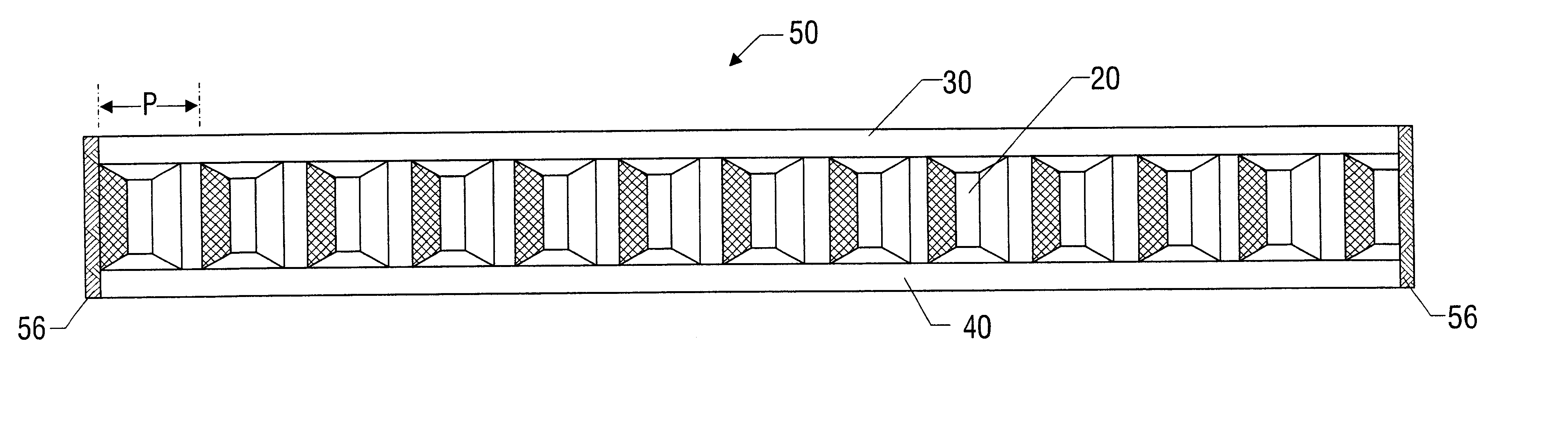
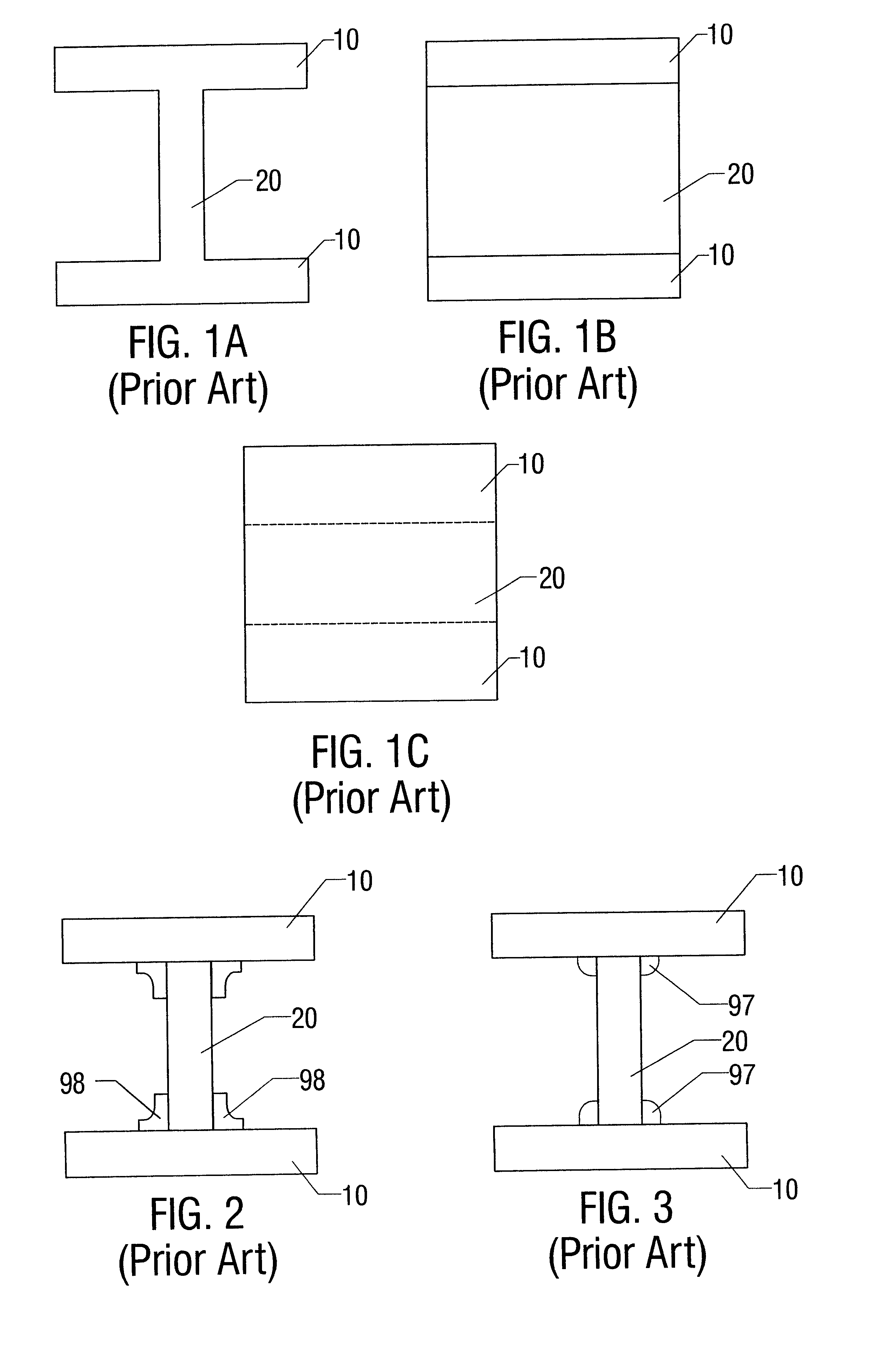
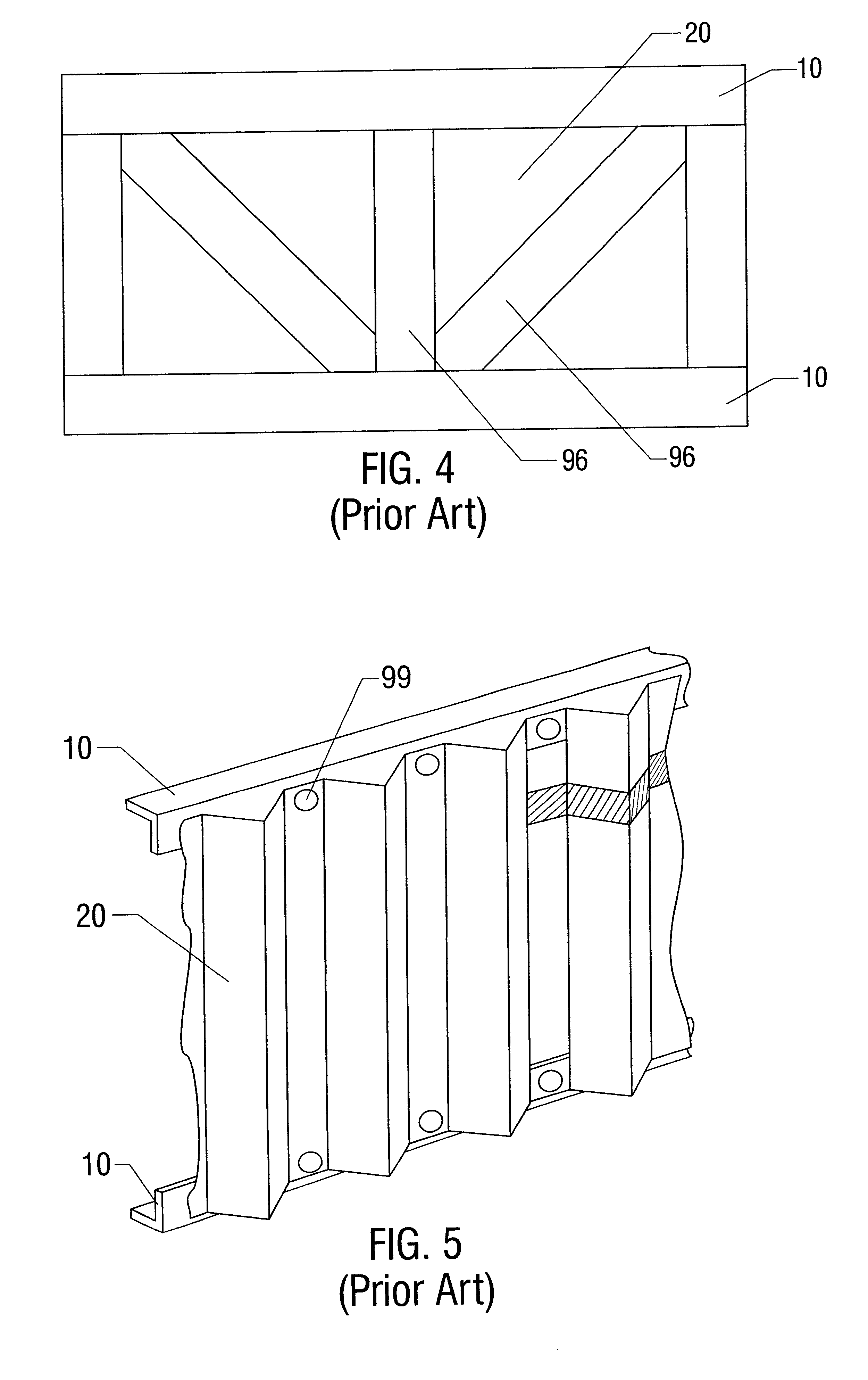
Corrugated web beam connected to a top tube and bottom tube
a technology of corrugated webs and beams, which is applied in the direction of girders, building repairs, joists, etc., can solve the problems of increasing manufacturing costs, reducing the weight of beams, and reducing the overall weight of beams, so as to reduce the overall weight of beams. the effect of reducing the overall weight of the beam
- Summary
- Abstract
- Description
- Claims
- Application Information
AI Technical Summary
Problems solved by technology
Method used
Image

Examples
Embodiment Construction
The following examples are included to demonstrate preferred embodiments of the invention. It should be appreciated by those of skill in the art that the techniques disclosed in the examples which follow represent techniques discovered by the inventor to function well in the practice of the invention, and thus can be considered to constitute preferred modes for its practice. However, those of skill in the art should, in light of the present disclosure, appreciate that many changes can be made in the specific embodiments which are disclosed and still obtain a like or similar result without departing from the spirit and scope of the invention.
Illustrative embodiments of the invention are described below as they might be employed to construct a structural beam. In the interest of clarity, not all features of an actual implementation are described in this specification. It will of course be appreciated that in the development of any such actual embodiment, numerous implementation-specif...
PUM
 Abstract
Description
Claims
Application Information