Pneumatic tire having electrically conductive rubber layer in land portion defined between circumferential grooves

a technology of pneumatic tires and conductive rubber, which is applied in the direction of special tyres, vehicle components, non-skid devices, etc., can solve the problems of discharging static electricity in the entirety of the tire to the ground surface, noise to radio, sparks,

Inactive Publication Date: 2002-07-09
BRIDGESTONE CORP
View PDF22 Cites 40 Cited by
  • Summary
  • Abstract
  • Description
  • Claims
  • Application Information

AI Technical Summary

Problems solved by technology

Hence there are problems such as noise to radio, electric shock, spark and the like.
According to this method, even if a product tire after vulcanization is mounted onto a passenger car and run over a long time to wear a ground contact region of the tread, the electrically conducting substance still remains in side walls of many grooves forming a tread pattern of the ground contact region, which can dissipate static electricity charged in the entirety of the tire to ground surface.
However, all of these methods have problems in the production and quality as mentioned below and are not necessarily satisfied.
For example, the antistatic effect is maintained at an initial running stage when the electrically conductive thick rubber layer is arranged in a central portion of the tread in its widthwise direction from the surface of the tread up to a rubber beneath the tread as disclosed in EP 0 658 452 and JP-A-8-34204, but there is a problem that if general-purpose carbon black is used as a filler, the electrically conducting path is interrupted at the running end stage due to the promotion of wearing of the electrically conductive layer to eliminate the antistatic effect.
Particularly, in order to maintain the effect of improving the wear resistance of the tread rubber or a tread cap rubber, the wear resistance of the electrically conductive rubber layer should be improved like the tread cap rubber, but it turns out that only the tread cap rubber actually contacts the ground and hence the antistatic effect can not be obtained.
Further, when several parts by weight of the electrically conductive carbon black based on 100 parts by weight of rubber ingredient is added to the tread rubber for the tire, the electric resistance of the tread rubber is lowered, but the low fuel consumption as a primary object of the tire is considerably degraded.
Also, the carbon black itself is considerably low in the reinforcing effect for the polymer and hence there is caused a problem of lowering the wear resistance of the tire tread.
In the method of applying the water-based rubber cement containing the electrically conductive carbon black onto the surface of the tread cap rubber, there is a problem in the stationary stability of the cement itself and hence there is a fear of causing phase separation.
Furthermore, it is required to use various stabilizers in order to prevent the blowing in the application, which degrades the durability of the resulting rubber cement film after the vulcanization and also results in the contamination of the mold for vulcanization.
Moreover, the rubber composition used in the tread cap rubber is hydrophobic, so that when the above water-based rubber cement is applied onto the tread cap rubber, drying takes a long time and the application unevenness is caused and hence the durability of the applied film is degraded.
Also, the adhesion force at the boundary between the tread cap rubber and the film of the water-based rubber cement lowers and hence boundary peeling is caused during the running of the tire, so that there is caused a problem that the antistatic effect is not obtained at the end stage of tire running due to the breakage of electrically conducting path.
That is, the shoulder portion is prematurely worn due to uneven wear in the tire as compared with the central portion of the tread to form a step difference between the central portion and the shoulder portion and hence the shoulder portion is not necessarily contacted with ground during the usual running.
Therefore, even if the electrically conductive rubber layer remains in a zone ranging from a tread end toward a sidewall portion, it is difficult to provide an antistatic effect because the rubber portion is already removed from the tread portion.
On the other hand, when the electrically conductive thin sheet is disposed on the groove, the effect is developed at an initial running stage, but the neighborhood of the groove edge is rapidly worn during the running and hence the sheet is not always contacted with ground.
Further, it has been confirmed that the electrically conductive rubber sheet is cut out by stones entered in the groove during the running and is not often retained in the groove on and after a middle running stage.

Method used


Image

  • Pneumatic tire having electrically conductive rubber layer in land portion defined between circumferential grooves
  • Pneumatic tire having electrically conductive rubber layer in land portion defined between circumferential grooves
  • Pneumatic tire having electrically conductive rubber layer in land portion defined between circumferential grooves

Examples


Embodiment Construction

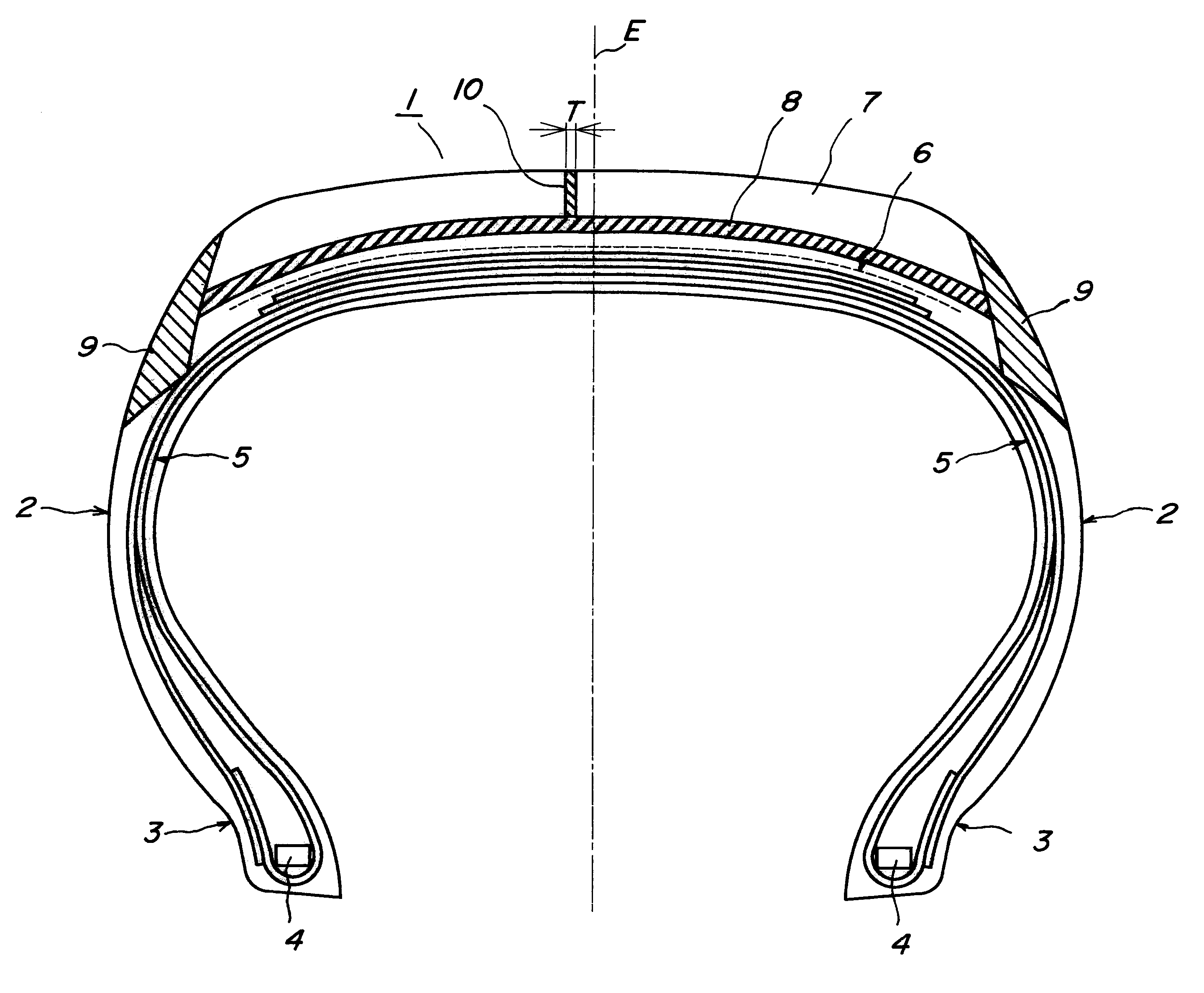
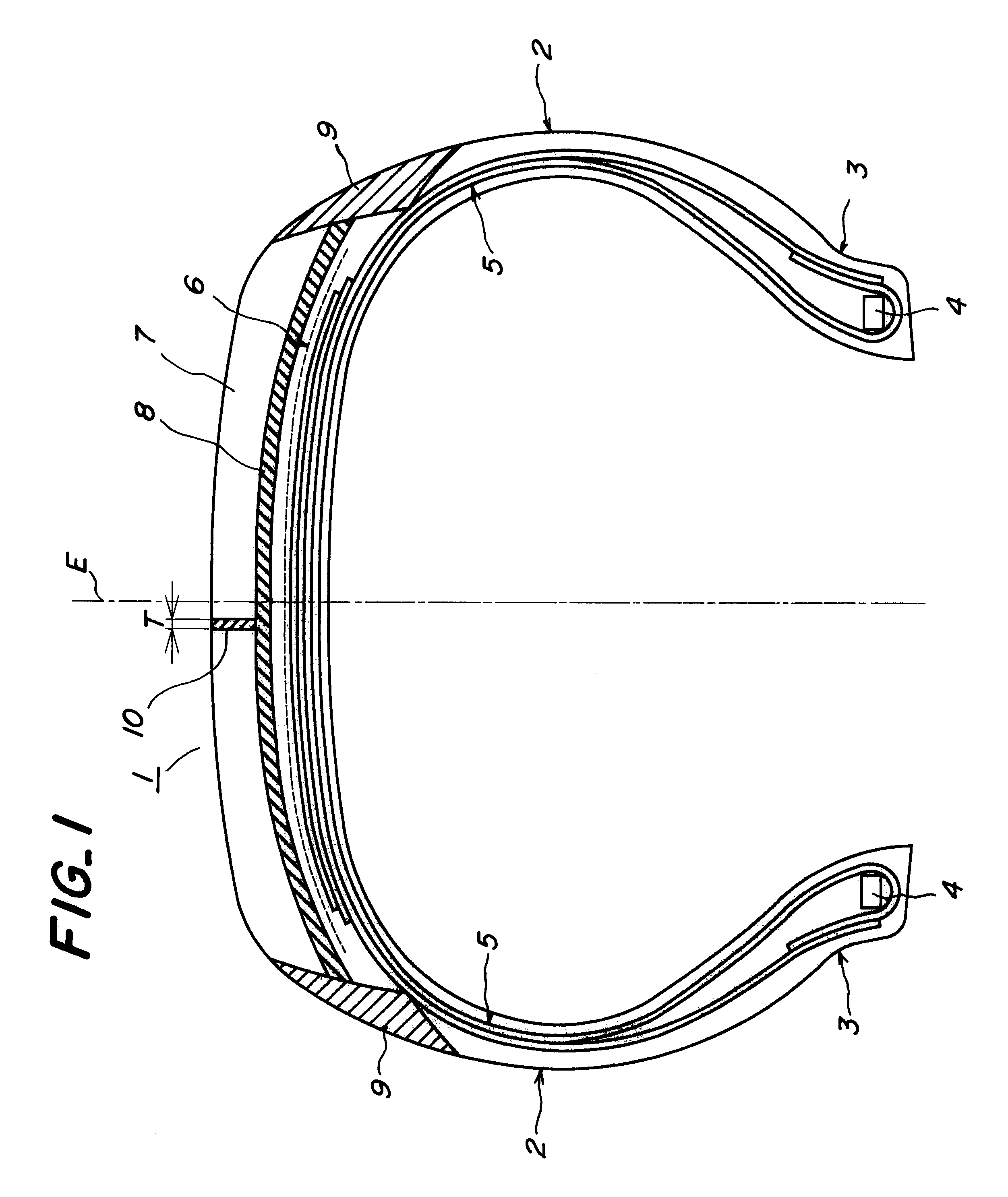
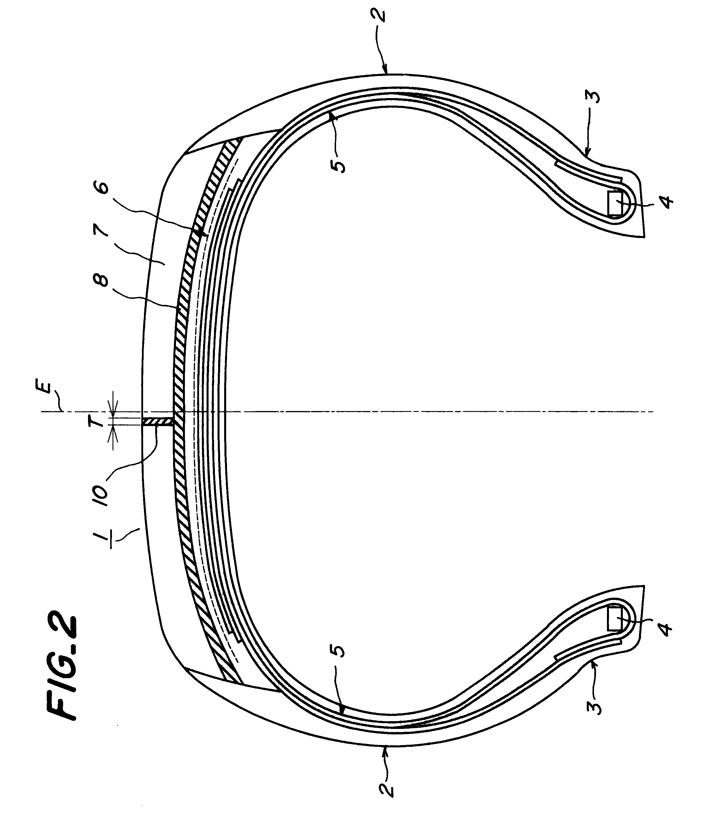
In the invention, the reason why the electrically conductive rubber layer is disposed in the region corresponding to 70% of the ground contact width of the new tire is based on the fact that since wearing of the shoulder portion or so-called shoulder wear is particularly and often caused on and after a middle stage of service life, even if the shoulder wear is caused, the electrically conductive rubber layer always contacts the road surface at the ground contact region. Further, the reason why the electrically conductive rubber layer does not cover the groove but extends in the tread rubber so as to sandwich both sides thereof in the widthwise direction between the tread rubbers is due to the fact that when the electrically conductive rubber layer is formed on the surface of the groove, it is cut out by wearing of the groove edge or stone-biting and does not contact the road surface on and after the middle stage of the service life.

In the invention, it is preferable that at least on...


PUM


Abstract

A pneumatic tire comprises a tread, in which a rubber layer having a specific resistance of not more than 106OMEGA.cm and a thickness of 0.1-1 mm forms a continuous layer extending in a circumferential direction of the tire while contacting with a surface portion of the tread having a specific resistance of not less than 108OMEGA.cm and a part of at least one member adjacent thereto in a radial direction.

Description

1. Field of the InventionThis invention relates to a pneumatic tire having an electrically conducting path formed by using an electrically conductive rubber composition. More particularly, it relates to a pneumatic tire having a low conductive tread compounded with a great amount of a filler such as silica for the improvement of low fuel consumption in which an electrically conducting path is formed in the tread by using an electrically conductive rubber composition for the prevention of electricity.2. Description of Related ArtThe pneumatic tire provided with a tread having a lower fuel consumption, particularly a silica-containing tread is high in electric resistance and low in the electric conductivity, so that static electricity generated from a vehicle body or a tire is hardly dissipated to ground surface through the tread. Hence there are problems such as noise to radio, electric shock, spark and the like.There are known the following methods for solving the above problems.As ...

Claims


Application Information

Patent Timeline
Patent Type & Authority Patents(United States)
IPC IPC(8): B60C19/00B60C19/08
CPCB60C19/08Y10S152/02
Inventor KOMATSU, HIDEKI
Owner BRIDGESTONE CORP
Why Eureka
Try Eureka