Shuttle car conveyor for conveyable material

a technology of conveying material and moving car, which is applied in the direction of conveying, manufacturing tools, transportation and packaging, etc., can solve the problems of complex system, difficult repair of components, and wear of custom-made tracks

Inactive Publication Date: 2002-07-09
CAPITAL ENG
View PDF22 Cites 18 Cited by
  • Summary
  • Abstract
  • Description
  • Claims
  • Application Information

AI Technical Summary

Benefits of technology

The system has a plurality of supports. Each support is for supporting conveyable material. The plurality of supports has a first support and a last support. The amount of supports is at least one more in number than the amount of cars forming the shuttle.

Problems solved by technology

The disadvantages of this design are: 1) there are a lot of parts to maintain since each pallet has rollers, bearings and axles; 2) the chain stretches, which affects the positioning of the downstream coil; 3) the custom-machined track wears out due to the high load of the roller (wheel); 4) the individual components are difficult to repair; 5) the system is costly due to the number of component parts and the need for custom track; and 6) the conveyor speed is limited.
The disadvantages of this design are: 1) the distance of traverse of the walking beam is limited by the length of the cylinder stroke, 2) the length of the beam conveyor is limited by manufacturing and shipping constraints, 3) the speed of the conveyor is limited by the operating speed of the drive cylinder, and 4) repairing the walking beam support rollers and elevating mechanisms requires major disassembly of the unit because the rollers and elevating mechanisms are fixed on foundations.

Method used


Image

  • Shuttle car conveyor for conveyable material
  • Shuttle car conveyor for conveyable material
  • Shuttle car conveyor for conveyable material

Examples


Embodiment Construction

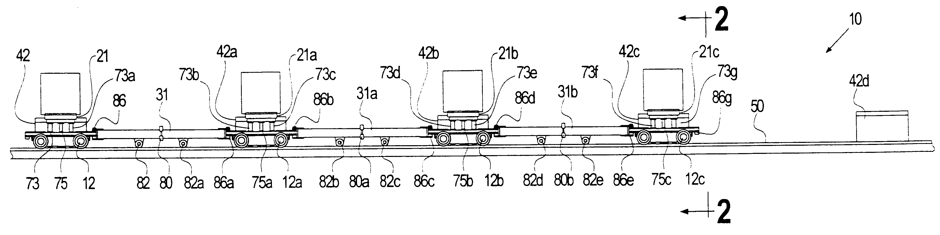
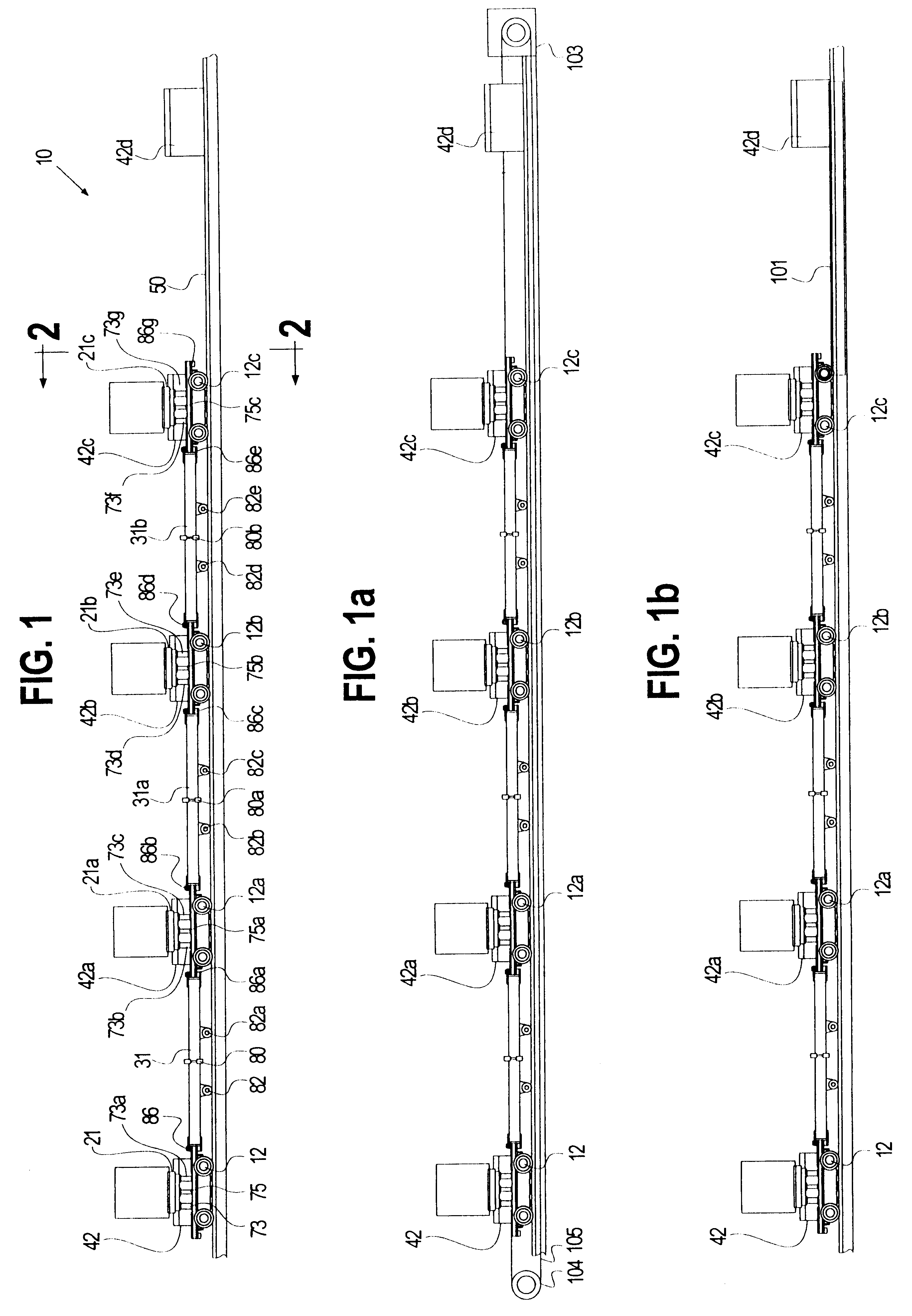
In accordance with the preferred embodiment of the invention shown in FIGS. 1-4, a four-car and five-saddle shuttle car conveyor system 10 is provided. The system has cars 12, 12a, 12b, 12c; elevating platens 21, 21a, 21b, 21c; spacer trolleys 31, 31a, 31b; coil saddles 42, 42a, 42b, 42c, 42d; and track 50. The plurality of cars connected by the spacer trolleys forms a shuttle car conveyor.

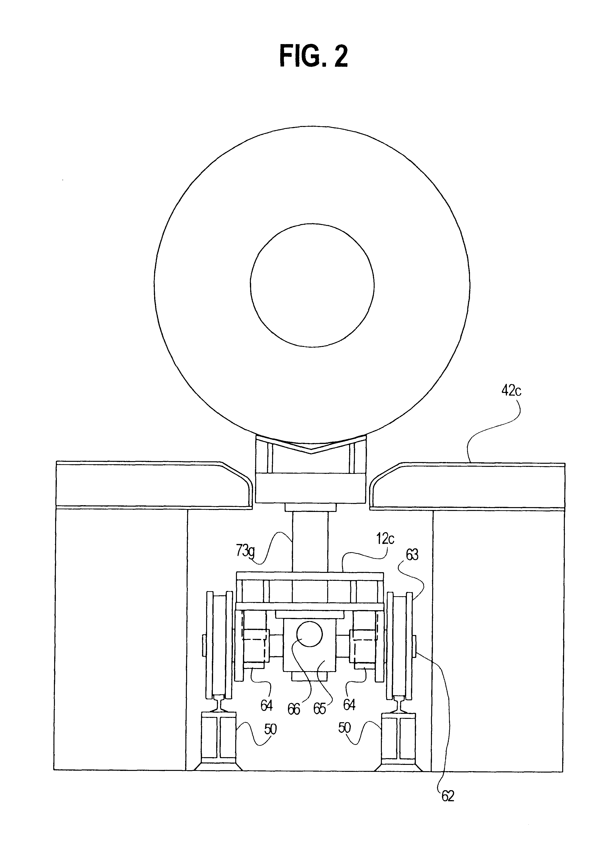
Each car is generally fabricated of steel plate. Each car has two axles 62 and four wheels 63. Each car axle 62 is mounted on two pillow block bearings 64. The wheels are typically rim toughed wheels. As shown in FIG. 3, the wheels are adapted to be disposed on standard rails of steel beam track 50. The cars shown are driven by electric or hydraulic motors 66. The electric motor is used to provide direct electric driven axles on said plurality of cars or in the case of a hydraulic motor, direct hydraulic motor driven axles on said plurality of cars. There are other methods to drive the shuttle car...


PUM

PropertyMeasurementUnit
distanceaaaaaaaaaa
lengthsaaaaaaaaaa
lengthaaaaaaaaaa

Abstract

An apparatus for conveying conveyable material. The apparatus includes a plurality of cars joined together by a plurality of spacers. The spacers couple the cars a fixed distance apart to form a shuttle. The shuttle is guided along a track between a first position and a second position. In the first position, the shuttle is aligned with a first group of supports. The shuttle in the first position receives conveyable material from the supports. The shuttle in the second position is aligned with a second group of supports. The shuttle disposes the conveyable material from each of the cars carrying the conveyable material to the second group of supports. A drive means repeatedly drives the shuttle between the first position and the second position. The cars remain the fixed distance apart during the driving between the first position and the second position.

Description

FIELDThe present invention relates to a shuttle for incrementally conveying materials and, more specifically, to a shuttle car conveyor for incrementally transporting conveyable materials downstream along a track.BACKGROUNDFlat rolled products in the metals industry are commonly wound into coils. These coils are transported by coil conveying systems such as roller chain conveyors and walking beam conveyors.The roller chain conveyors are comprised of a plurality of individual coil support pallets linked together by chain sections. Wheels mounted on bearings and axles support each pallet. Roll chain conveyors are generally driven by sprockets mounted on a rotating shaft. The rotating shaft is driven by a gear reducer and motor. The roller chain conveyor is guided by custom-machined track which is supported on structural steel. The disadvantages of this design are: 1) there are a lot of parts to maintain since each pallet has rollers, bearings and axles; 2) the chain stretches, which a...

Claims


Application Information

Patent Timeline
Patent Type & Authority Patents(United States)
IPC IPC(8): B21C47/24B61B5/00B61B5/02B65G25/02B65G25/00B21B39/00
CPCB21C47/24B61B5/025B65G25/02B21B39/00
Inventor MARKIEWICZ, JAMES S.
Owner CAPITAL ENG
Why Eureka
Try Eureka