
Level transmitter for a liquid container and method for determining the level in a liquid container

a level transmitter and liquid container technology, applied in the direction of machines/engines, using reradiation, instruments, etc., can solve the problems of reducing the useful container volume to an extent that cannot be neglected, increasing the susceptibility to faults of such a system, and expensive transmitters

Inactive Publication Date: 2002-07-16
MANNESMANN VDO AG
View PDF8 Cites 10 Cited by
  • Summary
  • Abstract
  • Description
  • Claims
  • Application Information

AI Technical Summary

Benefits of technology

An advantage of the level transmitter according to the present invention is that only the sensors are arranged in the liquid container. All the other components are located outside the liquid container. Since the sensors are a few square millimeters in size, and no electrical lines are required for making contact or for transmitting measured values to the sensors, the useful container volume is no longer reduced. Moreover, the level transmitter according to the invention comprises a very cost-effective design because one evaluation unit may be used to evaluate each of the sensors.
The present invention also relates to a measuring method in which no forces arise, for example, from movements of floats or levers. Consequently, the fastening of the sensors in the liquid container is configured with particular ease. As stated above, the transceiver unit detects measured oscillation values without the use of cables. Accordingly, the site of installation of all the other parts of the level transmitter may be selected freely. This has the advantage, in turn, that the electrical components no longer have to be arranged in regions of danger to them, with the result that the susceptibility to faults is reduced, and the outlay for reliable operation is reduced.
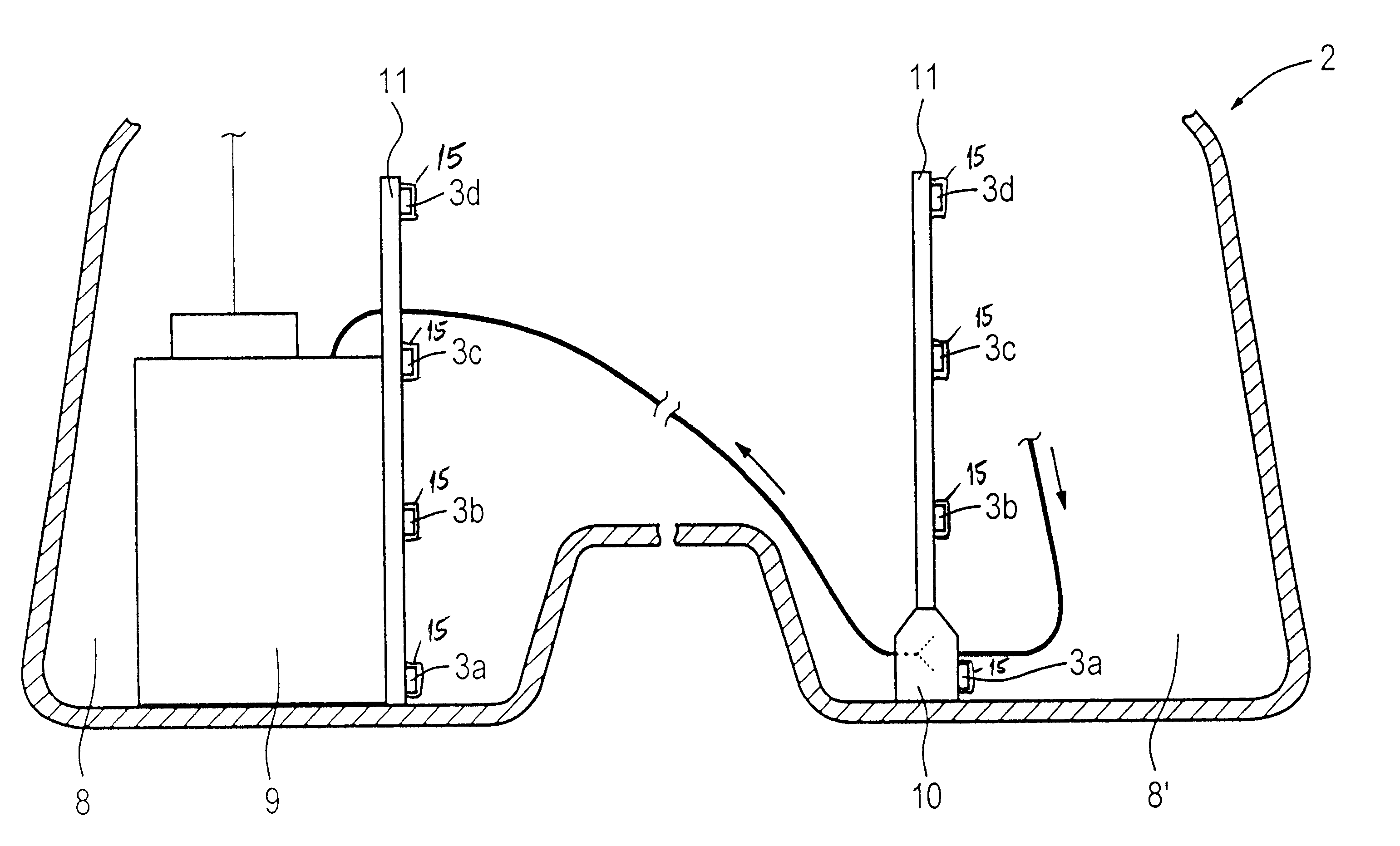
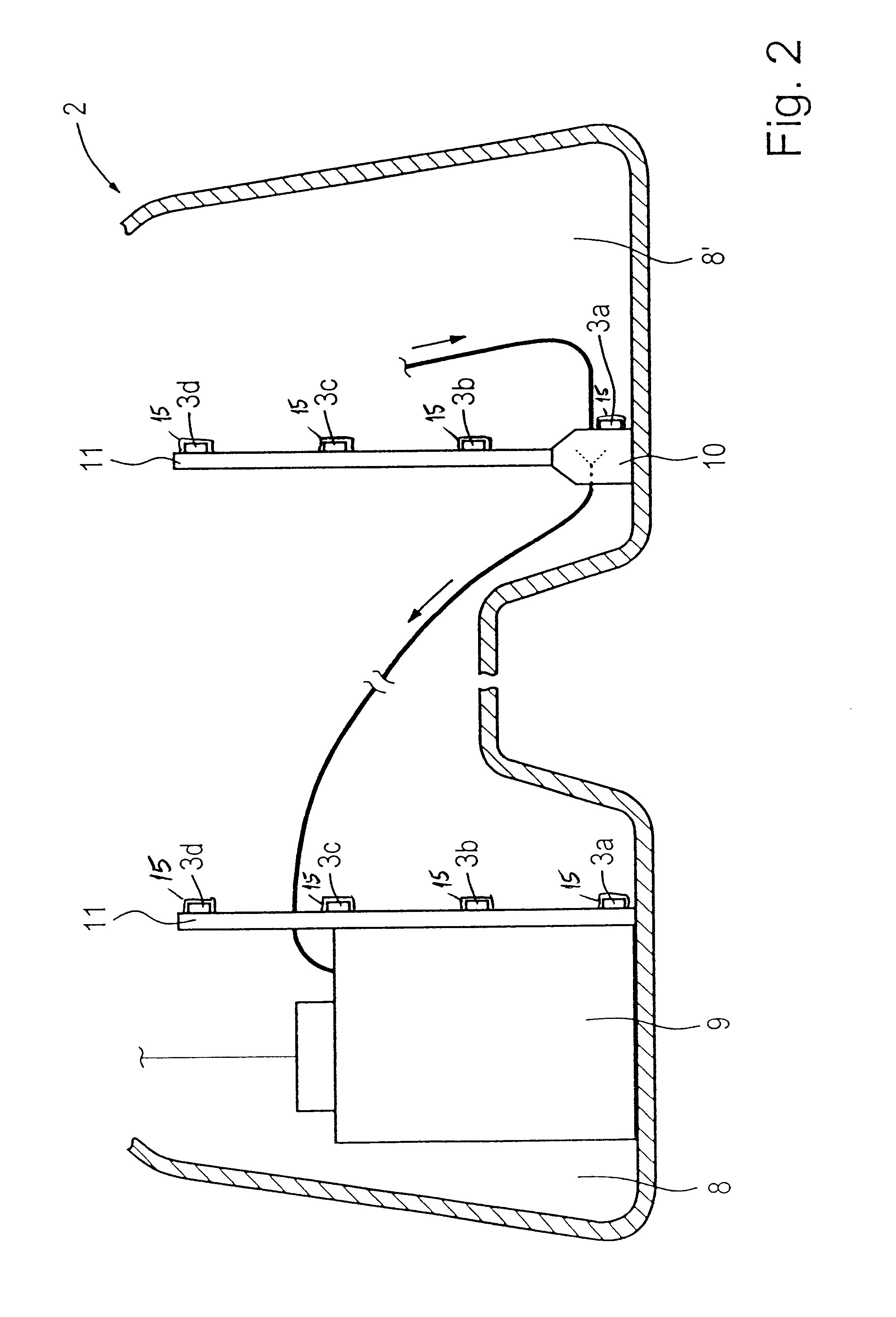
In a further embodiment, the sensors may be arranged on other built-in components in the liquid container. Thus, the outlay on assembly in the liquid container is eliminated when the sensors are mounted, for example, on the outside of a delivery unit or on a suction jet pump and are subsequently inserted with those components into the liquid container. For the purpose of an easier fastening of the sensors, the sensors may be arranged on a holder such that only the holder is to be fastened on the delivery unit.
Because the arrangement of the transceiver unit may be freely selected, its arrangement at a central point is particularly favorable for electrical measuring and control devices, since the electrical lines may be of particularly short design, and this leads to saving in weight and costs in addition to the better signal processing. However, it may also be advantageous in this case to arrange a transceiver unit separately in space.

Problems solved by technology

These transmitters are expensive because each level transmitter has a plurality of sensors, which are interconnected to form a sensitive measuring arrangement.
Additional expenditure on assembly results from the fact that the tube must be fastened to the bottom of the fuel tank.
In addition to the high initial outlay required for installing the multiplicity of level transmitters, there is a rise in the susceptibility to faults of such a system because of the number of components used.
A further disadvantage in the use of plural level transmitters in a liquid container is that the useful container volume is reduced to an extent which cannot be neglected.
If each of the sensors had the same physical dimensions, they would have the same oscillatory behavior and it would not be possible for the measured values to be assigned to the individual sensors by the evaluation unit.
The fact that most of the components of the level transmitter are arranged outside the liquid container also keeps the cost of assembly particularly low.

Method used


Image

  • Level transmitter for a liquid container and method for determining the level in a liquid container
  • Level transmitter for a liquid container and method for determining the level in a liquid container
  • Level transmitter for a liquid container and method for determining the level in a liquid container

Examples


Embodiment Construction

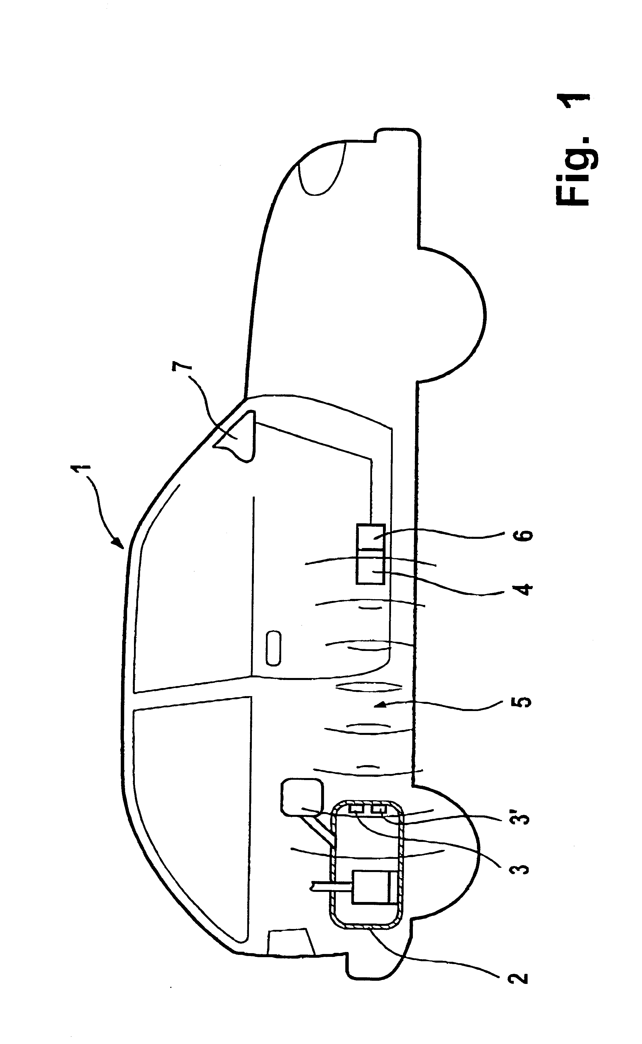
Referring to FIG. 1, a motor vehicle 1 includes a fuel tank 2 with sensors 3, 3' made from magnetostrictive material according to the present invention. The sensors 3, 3' are fastened to the inner wall of the fuel tank 2. A transceiver unit 4 is arranged in the front part of the motor vehicle 1. The transceiver unit 4 produces an alternating magnetic field 5 at intervals of, for example, one second and thereby stimulates the sensors 3, 3' to oscillate and produce ultrasonic waves. The frequency of the oscillations of the sensors 3, 3' is picked up by a receiver portion of the transceiver unit 4 and fed to an evaluation unit 6. The signal formed there is thereafter relayed to an evaluation unit 7 which displays the level to an operator of the motor vehicle 1.

FIG. 2 shows a further embodiment according to the present invention. In FIG. 2, a section of the fuel tank 2 is subdivided into two chambers 8, 8'. A delivery unit 9 for delivering the fuel to the engine of the motor vehicle is ...


PUM


Abstract

A level transmitter for a liquid container includes a simple construction without feed lines to the sensors through the container wall. The level transmitter has a plurality of sensors made from magnetostrictive material, which are excited to oscillate by an alternating magnetic field emitted by a transceiver unit. The sensors oscillate at different frequencies which are detected by the transceiver unit. The detected signals are fed to an evaluation unit and used to form a signal for the level. The level transmitter and the method are particularly suitable for use in fuel tanks in motor vehicles.

Description

1. Field of the InventionThe present invention relates to a level transmitter for a liquid container, more specifically a fuel tank in a motor vehicle, having a plurality of sensors and a method for determining the level in the liquid container.2. Description of the Related ArtLevel transmitters for determining levels in liquid containers are much used in practice and are therefore known. Depending on the site of installation of the liquid container, the containers can take the most varied forms. For example, the liquid containers used in motor vehicles such as fuel tanks are adapted very strongly to prescribed spaces. Thus, many of the fuel tanks currently used have two or more chambers. A level transmitter is arranged in each of these chambers to determine a level in the liquid container having more than one chamber. In these cases, the level transmitters comprise float-actuated lever transmitters or transmitters comprising a plurality of sensors.European Patent reference EP 0 690...

Claims


Application Information

Patent Timeline
Patent Type & Authority Patents(United States)
IPC IPC(8): G01F23/296
CPCG01F23/2963G01F23/2965G01F23/2967
Inventor ECK, KARL
Owner MANNESMANN VDO AG
Learn More