Auger-like drywall screw

a drywall screw and screw head technology, applied in the field of drywall screws, can solve the problems of unsightly and likely oversize of larger fastening devices, and achieve the effect of improving holding power and easy removal

Inactive Publication Date: 2002-07-16
BLACK & DECKER INC
View PDF6 Cites 81 Cited by
  • Summary
  • Abstract
  • Description
  • Claims
  • Application Information

AI Technical Summary

Benefits of technology

One object of this invention is to provide a relatively small screw with improved holding power for use in dry wal

Problems solved by technology

Devices such as picture hangers typically use a nail and a fulcrum device; the nail can easily come out of the wall or it may tear th

Method used


Image

  • Auger-like drywall screw
  • Auger-like drywall screw
  • Auger-like drywall screw

Examples


Embodiment Construction

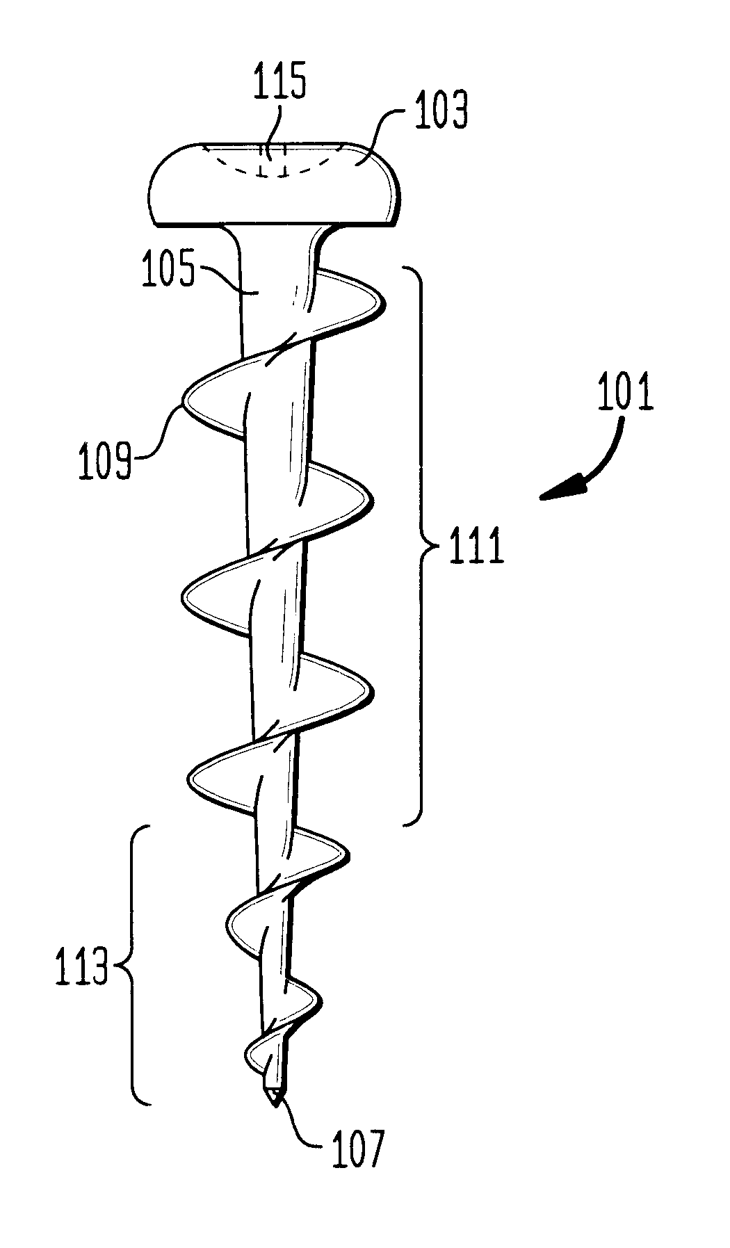
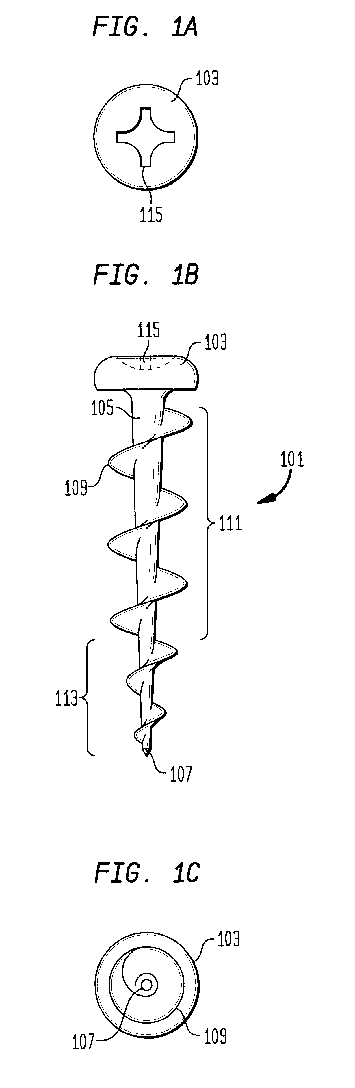
With reference to FIG. 1B is seen an idealized side view of the novel screw 101 having a head 103 from which depends a shank 105 that tapers to the tip 107, the taper being largest at the head and becoming smaller towards the tip. Disposed on the shank is a helical thread 109 having the geometry of an auger. For the main portion of the thread 111 the pitch diameter is constant, like a machine screw. For the bottom portion of the thread 113, the pitch diameter tapers like a wood screw. FIG. 1A is a top view showing the head 103 and a cavity 115 adapted for receiving a Phillips-type screw driver, although it should be understood that any type of driver cavity is suitable. FIG. 1C is a bottom view.

The advantage of this novel screw is that the thread is much wider than the shank, thereby providing a large surface area for cutting into dry wall. The large thread (compared with the shank diameter) provides significant pull-out resistance and holding power. It is preferred that the pitch d...


PUM


Abstract

The present invention relates to a novel screw for use with dry wall and for hanging articles therefrom. This invention provides a screw with a head adapted for engagement with a driving tool, a shank whose diameter decreases from the head to a distal end, and a helical thread with a pitch diameter of at least about twice the largest minimum diameter of the shank. The thread including a geometry of an auger.

Description

1. Field of the InventionThis invention relates to a novel screw for use with dry wall (gypsum plasterboard, Sheetrock, etc.) for the homeowner in hanging articles therefrom.2. The State of the ArtScrews have existed for many years and are based on the principle of the inclined plane providing a wedging action to force the head of the screw into the substrate. Different screws have been developed for different materials, principally for wood and sheet metal, but also for dry wall. A typical dry wall screw has a body of a constant diameter and a thread designed to cut into both the dry wall and the fixture to which it is support (often a metal stud).Homeowners typically hang pictures, shelves, plants, and other devices or decoration from their interior walls. Devices such as picture hangers typically use a nail and a fulcrum device; the nail can easily come out of the wall or it may tear through the Sheetrock. Larger fastening devices can be unsightly and are likely oversized for the...

Claims


Application Information

Patent Timeline
IPC IPC(8): F16B25/00F16B33/00F16B33/02
CPCF16B25/00F16B25/0026F16B25/0047
Inventor GAUDRON, PAUL
Owner BLACK & DECKER INC
Why Eureka
Try Eureka