Spiral wound transducer

a transducer and spiral wound technology, applied in the field of transducers, can solve the problems of capacitor plate height, and many types of previous transducers consume substantial amounts of electrical power

Inactive Publication Date: 2002-07-16
UNIV NORTH CAROLINA CHARLOTTE
View PDF7 Cites 102 Cited by
  • Summary
  • Abstract
  • Description
  • Claims
  • Application Information

AI Technical Summary

Benefits of technology

FIG. 3(a-b) shows a cross-section of a small section of an SWT in an unpow...

Problems solved by technology

Many types of previous transducers consume substantial amounts of electrical power.
For example, electromagnetic devices like solenoids consume electrical energy when they are energized but not moving (at a contr...

Method used


Image

  • Spiral wound transducer
  • Spiral wound transducer
  • Spiral wound transducer

Examples


Embodiment Construction

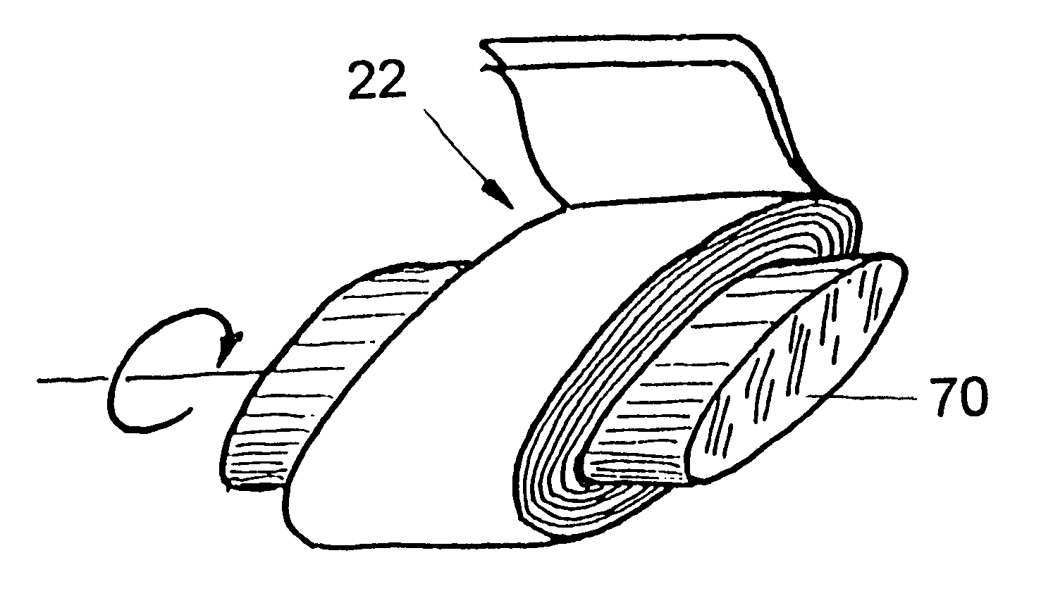
The present invention provides a spiral wound transducer (SWT) of the invention is an array of metallized plastic capacitive force cells prepared by assembly and treatment of flexible and stiff layers. The cells compress when the device is electrically powered to produce an overall deformation.

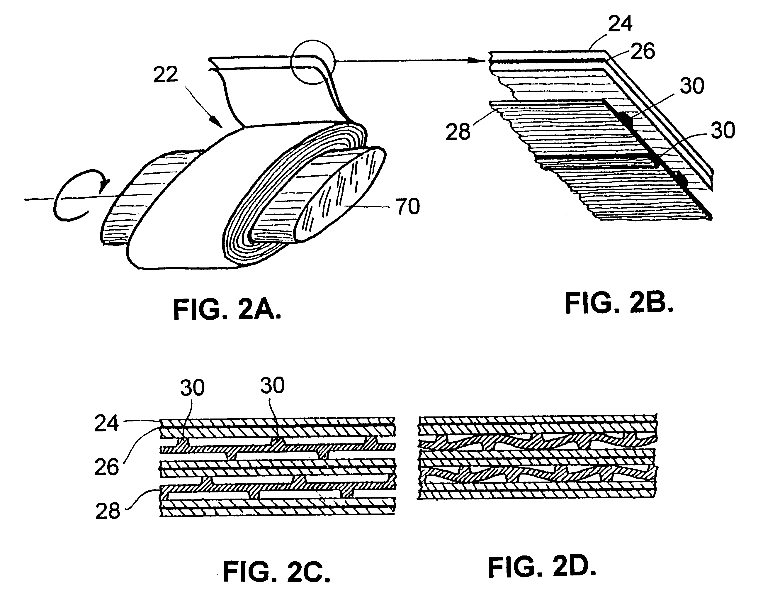
Referring to the figures, a first embodiment of the invention is shown in FIG. 2 (a-d). FIG. 2a is a perspective view of an SWT assembly 22, with a detail thereof being shown in FIG. 2b. FIG. 2c shows a cross-section of an unpowered, relaxed SWT and FIG. 2d shows a cross-section of a powered, compressed SWT. The transducer as shown comprises a double plastic layer in the form of two continuous shapes wound on a central form 70B1. This form may be either conductive or insulating. It typically remains in place and may be used to electrically and / or mechanically attach the transducer to an external system. One of the plastic layers 24 is stiff and contains a conductive embedded sheet 26. The stif...


PUM


Abstract

A transducer compressible in response to electric power, including a flexible, conductive plastic layer microimprinted with a pattern and a stiff plastic layer containing a conductive embedded sheet.

Description

CROSS-REFERENCE TO RELATED DOCUMENTSThis invention is disclosed in Disclosure Document No. 419672, filed May 19, 1997 with the US Patent Office.1. Field of the InventionThis invention relates to transducers, and in particular, relates to a spiral wound transducer having an array of metallized plastic capacitive force cells.2. Description of the Related ArtTransducers are devices which convert one form of input energy to a different form of output energy. Thus, electromechanical transducers may convert electrical energy to mechanical energy, due to the electrostatic attraction caused by two opposing and oppositely charged plates which move together in response to a voltage applied between the plates, converting the input electrical energy to mechanical energy.Integrated force arrays (IFAs) are planar, thin film membrane actuators that act as transfer devices for electrostatic force. They are capable of large amplitude motion and are capable of significant work per unit volume. FIG. 1...

Claims


Application Information

Patent Timeline
IPC IPC(8): H02N1/00
CPCH02N1/006
Inventor BOBBIO, STEPHEN M.
Owner UNIV NORTH CAROLINA CHARLOTTE
Why Eureka
Try Eureka