
Print system and a sheet-processing device suitable for such a print system

a printing system and printing system technology, applied in the direction of instruments, electrographic processes, apparatus for dispensing discrete objects, etc., can solve the problems of paper jams, inconvenient printing for automatic vending machines, and the lik

Inactive Publication Date: 2002-07-16
MINOLTA CO LTD
View PDF21 Cites 31 Cited by
  • Summary
  • Abstract
  • Description
  • Claims
  • Application Information

AI Technical Summary

Benefits of technology

When the user is identified in this manner, the job specified by the user is automatically carried to the sheet outlet so that the user can get his or her job smoothly without having any unnecessary confusion.
In this print system, the receipt on which the predetermined coded information has been printed is issued, and the user can take out the job by inputting the predetermined coded information printed on the receipt. It is not necessary for the user to memorize the predetermined coded information such as a password code assigned to the user, and the user can readily take out the job as long as he or she has the receipt.

Problems solved by technology

Since such image output apparatuses are usually installed in places where a number of unspecified people come around, it is feared that an output print (a sheet bearing a printed image) might be taken away by someone other than the user before he or she knows it.
However, the above-mentioned conventional sorter device requires a plurality of outlets and some of the outlets have to be placed at positions that are inconvenient in taking prints out.
Another problem is that since the print should be bent with a comparatively small curvature when it is sorted, paper jams tend to occur.
However, this system is assumed to be used in an office where the user can be specified, and is not suitable for a printer of the automatic vending machine type that is used by a number of unspecified people.
Moreover, in the image output apparatus of this type, a considerable period of time is required for printing an image, with the result that the job might be left for a long time without being taken out because of the fact that the user becomes impatient to wait, or fails to come and pick up the job at the specified time.

Method used


Image

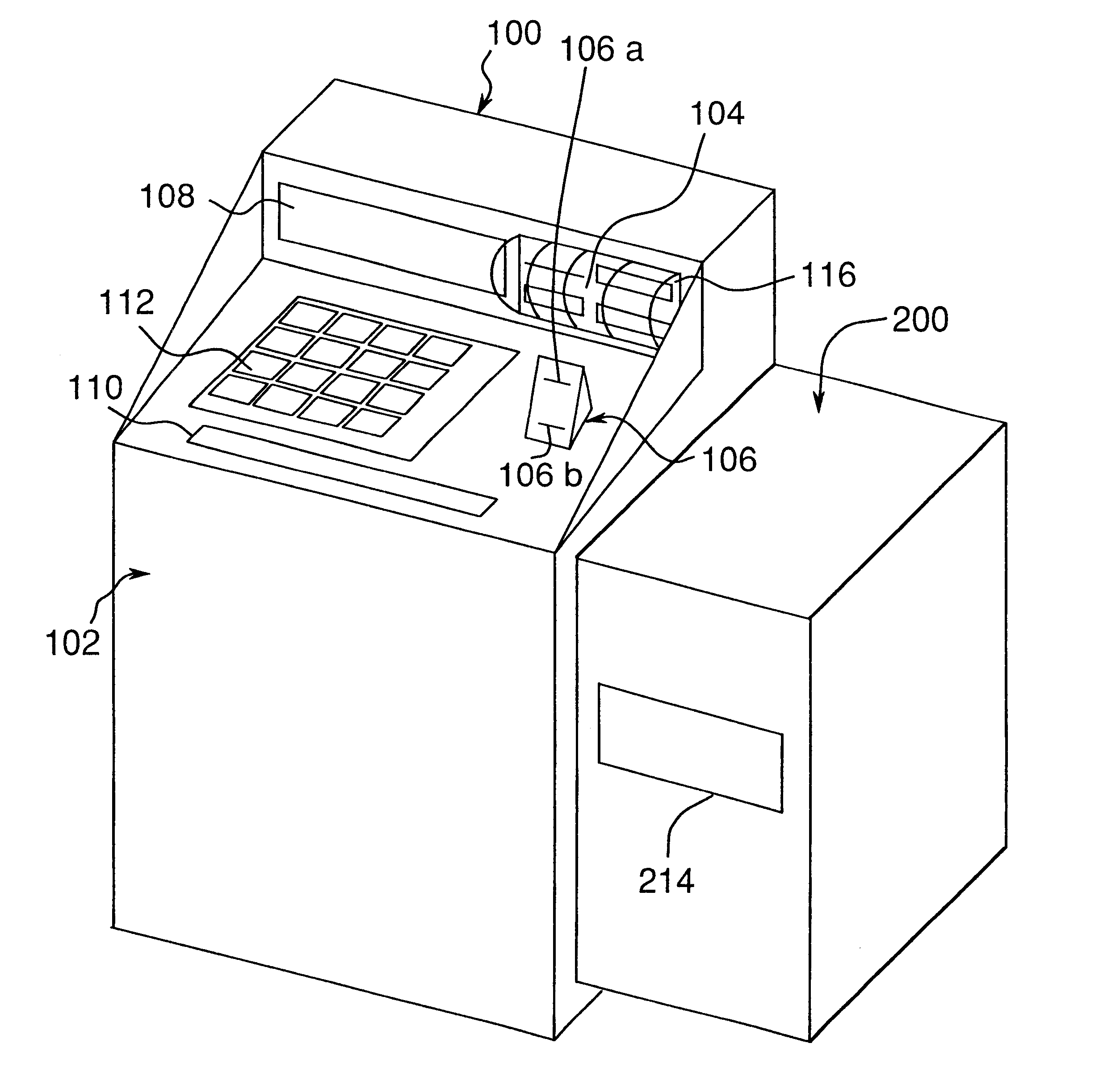
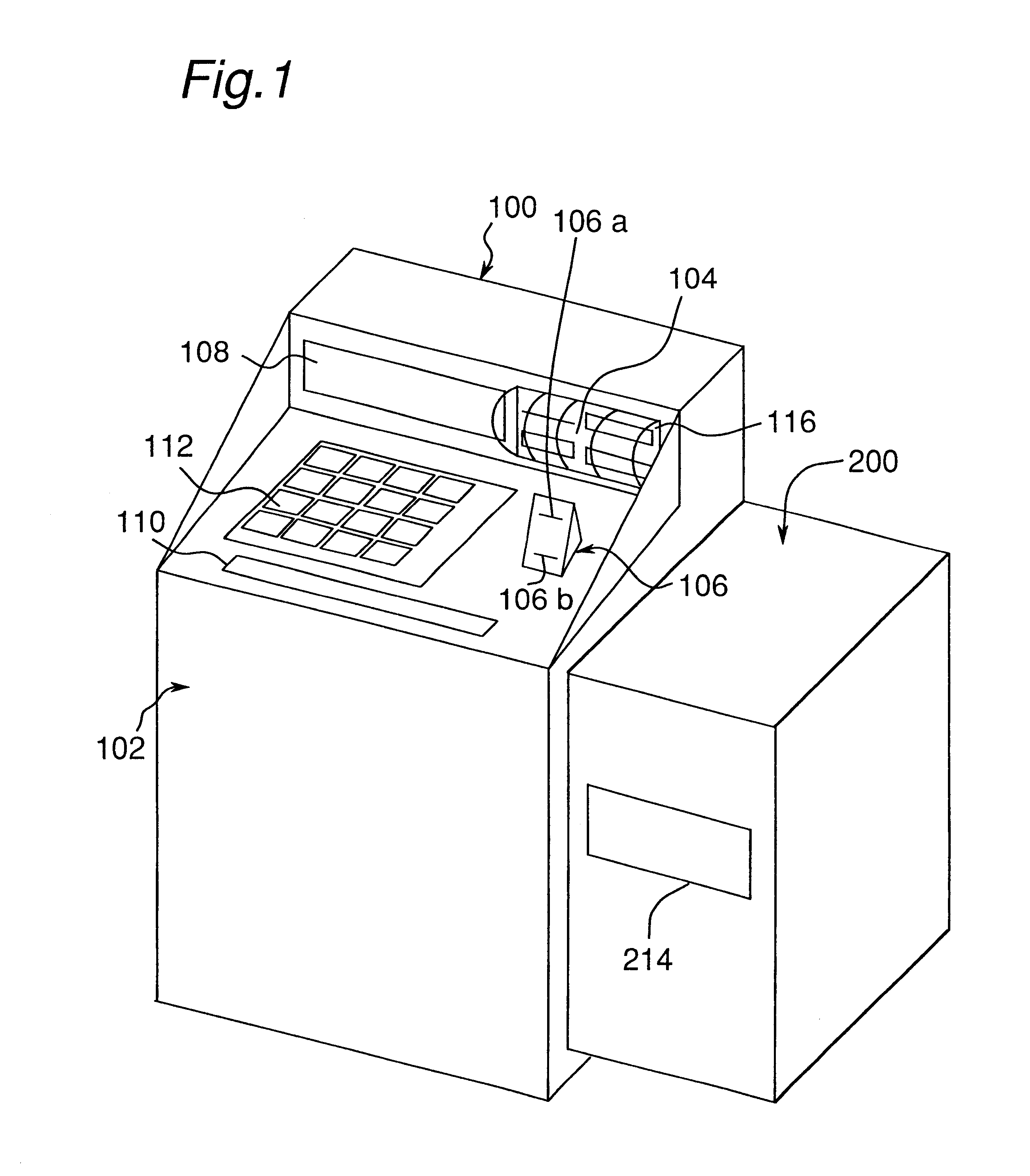
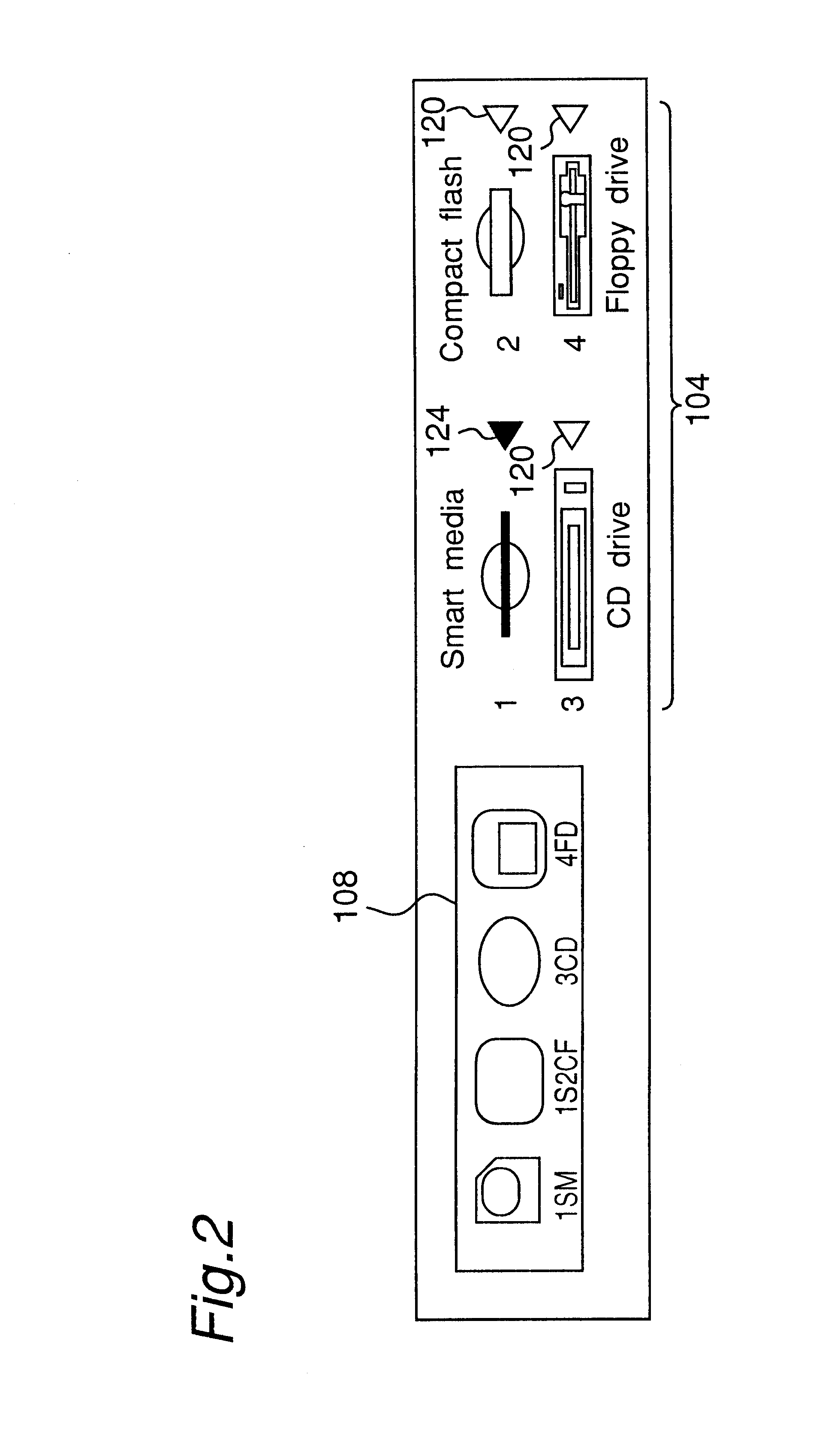
  • Print system and a sheet-processing device suitable for such a print system
  • Print system and a sheet-processing device suitable for such a print system
  • Print system and a sheet-processing device suitable for such a print system

Examples


second embodiment

FIG. 9 shows the sheet-processing device of the present invention. In this Figure, the same reference numbers indicate the same members in FIG. 6. In the present embodiment, the level of the outlet 214 is set in a level different from the level of the rear end of the conveyor belt 20. In the sheet-processing device of the present embodiment, it is not necessary to. provide a door with a lock at the door 215 of the outlet 214. Therefore, FIG. 9 shows a state in which, among the five stages of storage bins 30, paper W in the storage bin 30 on the second stage from below can be taken out.

In such a construction, it is not possible to take out paper W unless the position of the storage bin 30 is shifted to a position facing the outlet 214 by using a specific operation such as an entry of a password, etc. It is of course preferable to install the door 215 from the viewpoint of dust protection and security; however, it is not necessary to provide a locking mechanism.

Here, in order to impro...

fifth embodiment

FIGS. 11 and 12 show a sheet-processing device in accordance with the present invention. In these Figures, the same reference numbers indicate the same members or corresponding members in FIGS. 5 and 6. In this embodiment, a direction switching member 500 is installed at the rear end of the conveyor belt 20, and a plurality of packaging boxes 60 are placed side by side below the conveyor belt 20. On the side of the conveyor belt 20, a housing container (maintaining section) 90 is placed along the conveyor belt 20. The housing container 90 is separated by partition walls to provide respective spaces, each having the size of the packaging box 60; thus, the packaging boxes 60 are housed therein.

After the predetermined processes have been carried out on the paper W on the main body side, the paper W is discharged onto the conveyor belt 20 by a paper discharge roller 80, transported by the conveyor belt 20, switched downward in its direction by a direction switching member 100, and put i...

first embodiment

Therefore, in addition to the effects of the first embodiment, the sheet-processing device of the present embodiment provides the following effects.

1. It is possible to ensure the inserting process into the box by stacking the sheets of paper in an offset state in the trap section T.

2. It is possible to simplify the device by providing the sorter section 300 as boxes, etc.

3. It is possible to ensure the security and also to provide easy handling by providing the trap section T as boxes.

4. It is possible to ensure the security and also to provide easy handling by providing the trap section T as bags.

Additionally, the present invention is not intended to be limited by the above-mentioned embodiments, and various modifications and improvements may be made. For example, the sorter section may have a shape different from the above-mentioned embodiments, and for example, an elevator system, a rotation system, etc. may be adopted. Moreover, the transport means is not limited to the conveyo...


PUM


Abstract

When a fare is inserted, a receipt on which a password assigned to the user is printed is issued, and a sheets each bearing a printed image is housed in a storage bin or a storage box. When the password printed on the receipt is inputted, the corresponding storage bin (storage box) is shifted to a sheet outlet, thereby allowing the user to take this out. Thus, it is possible to provide a print system that is superior in the operability and allows the user to positively obtain his or her own job, and a sheet-processing device suitable for such a system.

Description

This application is based on application No. 11-134130 filed in Japan, the contents of which is hereby incorporated by reference.1. Field of the InventionThe present invention relates to a print system and a sheet-processing device preferably used for the print system and, more specifically, to an image output apparatus of an automatic vending machine type and a device connected therewith for preventing prints from being taken away by others.2. Description of the Related ArtIn recent years, image output apparatuses of the automatic vending machine type, which output image data picked up by a digital camera, etc., as a printed image on a sheet of paper, have been proposed. Since such image output apparatuses are usually installed in places where a number of unspecified people come around, it is feared that an output print (a sheet bearing a printed image) might be taken away by someone other than the user before he or she knows it. Consequently, it is necessary for the user to wait f...

Claims


Application Information

Patent Timeline
Patent Type & Authority Patents(United States)
IPC IPC(8): G03G21/02G03G15/00
CPCG03G15/6538B65H2408/113
Inventor WADA, KENICHI
Owner MINOLTA CO LTD
Learn More