Ball joint

a ball joint and ball joint technology, applied in the field of ball joints, can solve the problems of excessive lash in the ball joint, vague or other undesirable characteristics, and avoid the effect of lashing

Inactive Publication Date: 2002-07-23
KOYO STEERING SYST OF NORTH AMERICA +2
View PDF20 Cites 47 Cited by
  • Summary
  • Abstract
  • Description
  • Claims
  • Application Information

AI Technical Summary

Problems solved by technology

During the life of the vehicle, the parts of the ball joint inevitably wear, producing lash in the ball joint.
Excessive lash is undesirable.
This movement can also produce vagueness or other undesirable characteristics in the steering system.

Method used


Image

  • Ball joint
  • Ball joint
  • Ball joint

Examples


Embodiment Construction

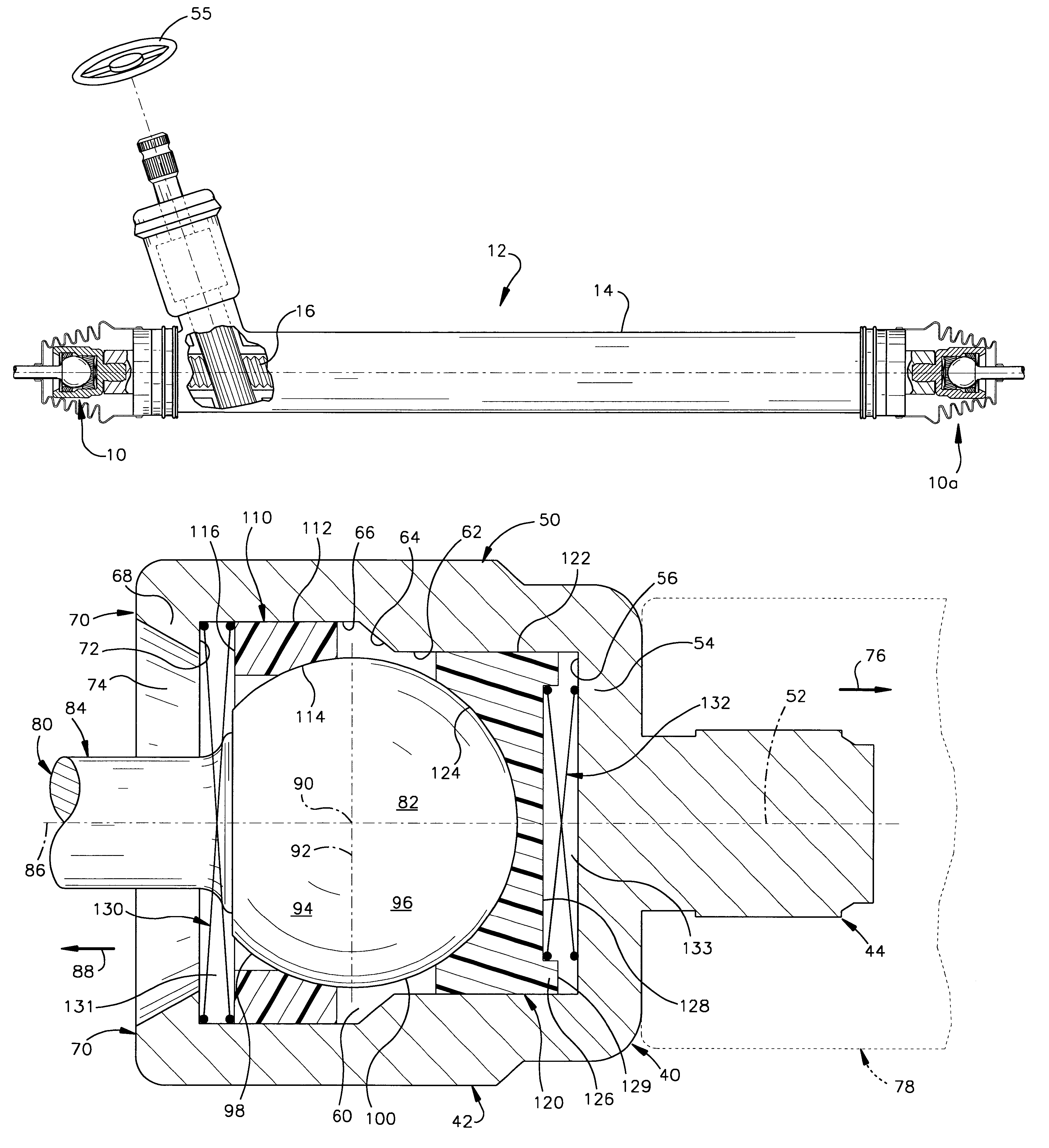
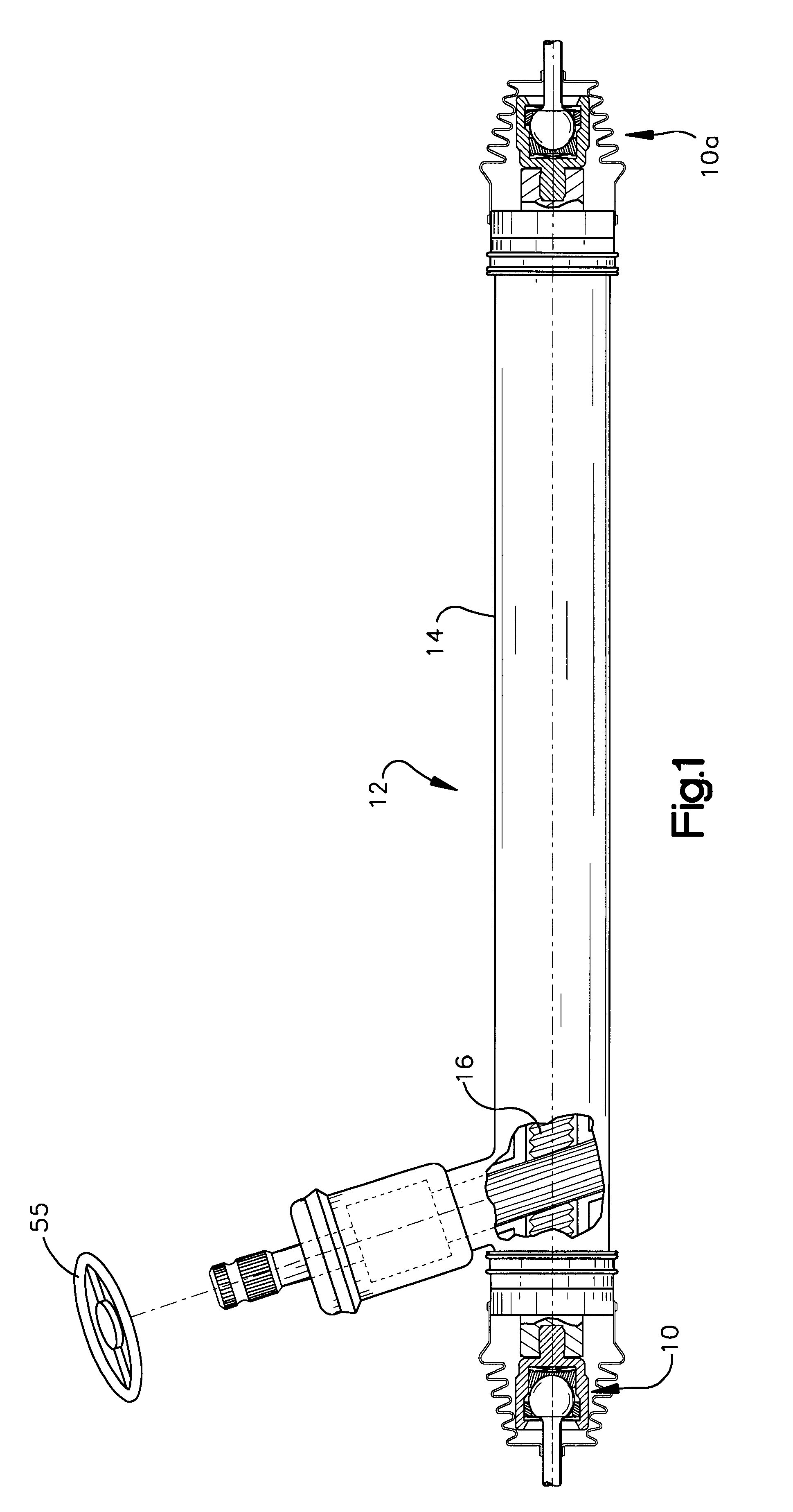
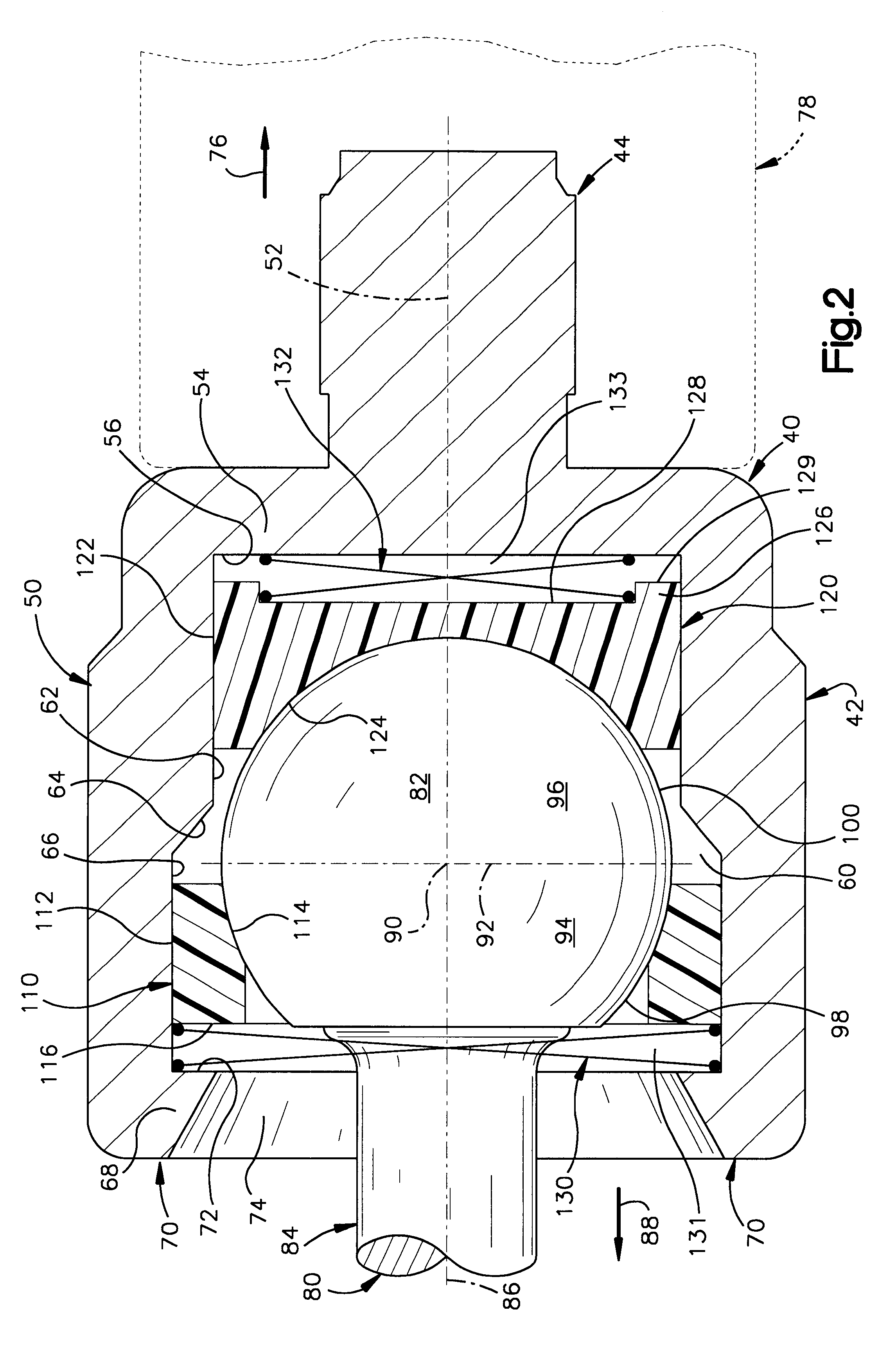
The present invention relates to a rack and pinion vehicle steering gear, and in particular relates to a ball joint for connection between a steerable vehicle wheel and a rack of a rack and pinion steering gear. The present invention is applicable to various ball joint constructions. As representative of the present invention, FIG. 1 illustrates a ball joint 10 that forms a part of a fluid power assisted vehicle rack and pinion steering gear 12. An identical ball joint 10a is located at the opposite end of the rack 16. Because the two ball joints 10 and 10a are identical in construction, only the ball joint 10 is described in detail below.

The steering gear 12 (FIG. 1) includes a housing 14. A steering member in the form of a rack 16 is supported by and is movable relative to the housing 14. The ball joints 10 and 10a are located at opposite ends of the rack 16. The ball joints 10 and 10a connect the rack 16 with suitable steering linkage (not shown) such as tie rods for effecting st...


PUM


Abstract

A ball joint (10) includes a socket (40) with a housing (42) and a stem portion (44). The housing (42) defines a chamber (60). A ball stud (80) has a ball portion (82) in the chamber (60) and a stud portion (84) extending from the ball portion. The ball portion (82) has a center (90) and the stud portion (84) has an axis (86) intersecting the center. The ball portion (82) has an equator (92) extending perpendicular to the axis (86) and dividing the ball portion into first and second hemispheres (94, 96). First and second bearings (110, 120) are located in the chamber (60) and engage the first and second hemispheres (94, 96), respectively, of the ball portion (82). First and second dampers (130, 132) act between the socket (40) and the respective first and second bearings (110, 120) and bias the first and second bearings toward the equator (92) and provide first and second clearances (131, 133), respectively, between the socket (40) and the first and second bearings.

Description

1. Technical FieldThe present invention relates to a ball joint for connection between a steerable vehicle wheel and a rack of a rack and pinion steering gear.2. Description of the Prior ArtA vehicle rack and pinion steering gear includes a rack that is movable axially to effect steering movement of steerable wheels of the vehicle. The movement of the rack is transmitted through steering linkage to the steerable wheels. The steering linkage typically includes a pair of ball joints on opposite ends of the rack. Each ball joint includes a ball stud in a socket. One or more bearings are interposed between the ball stud and the socket. During the life of the vehicle, the parts of the ball joint inevitably wear, producing lash in the ball joint. Excessive lash is undesirable.The rack and pinion steering gear is typically mounted to the vehicle frame by resilient bushings. The bushings enable a small amount of movement of the steering gear relative to the frame. This movement helps to tak...

Claims


Application Information

Patent Timeline
Patent Type & Authority Patents(United States)
IPC IPC(8): B62D3/12B62D3/00B62D7/22B62D7/00F16C11/06
CPCB62D3/12B62D7/22F16C11/0638Y10T403/32762Y10T403/32811F16C25/04
Inventor SPAGNUOLO, STEVEN P.
Owner KOYO STEERING SYST OF NORTH AMERICA
Why Eureka
Try Eureka