Polyaxial bone screw with cam capture

a technology cam capture, which is applied in the field of polyaxial bone screws, can solve problems such as difficult or impossible to do, and achieve the effects of preventing unintentional disassembly, convenient, and secure attachment to each other and to bon

Active Publication Date: 2008-06-12
JACKSON
View PDF99 Cites 112 Cited by
  • Summary
  • Abstract
  • Description
  • Claims
  • Application Information

AI Technical Summary

Benefits of technology

[0009]Therefore, objects of the invention include: providing an implant wherein all of the parts remain together and do not separate; providing a lightweight, low profile polyaxial bone screw that assembles in such a manner that the components cooperate to create an overall structure that prevents unintentional disassembly; providing a polyaxial bone screw with features that provide adequate frictional or gripping surfaces for bone implantation tools and may be readily, securely fastened to each other and to bone; and providing apparatus and methods that are easy

Problems solved by technology

This is sometimes very dif

Method used


Image

  • Polyaxial bone screw with cam capture
  • Polyaxial bone screw with cam capture
  • Polyaxial bone screw with cam capture

Examples


Embodiment Construction

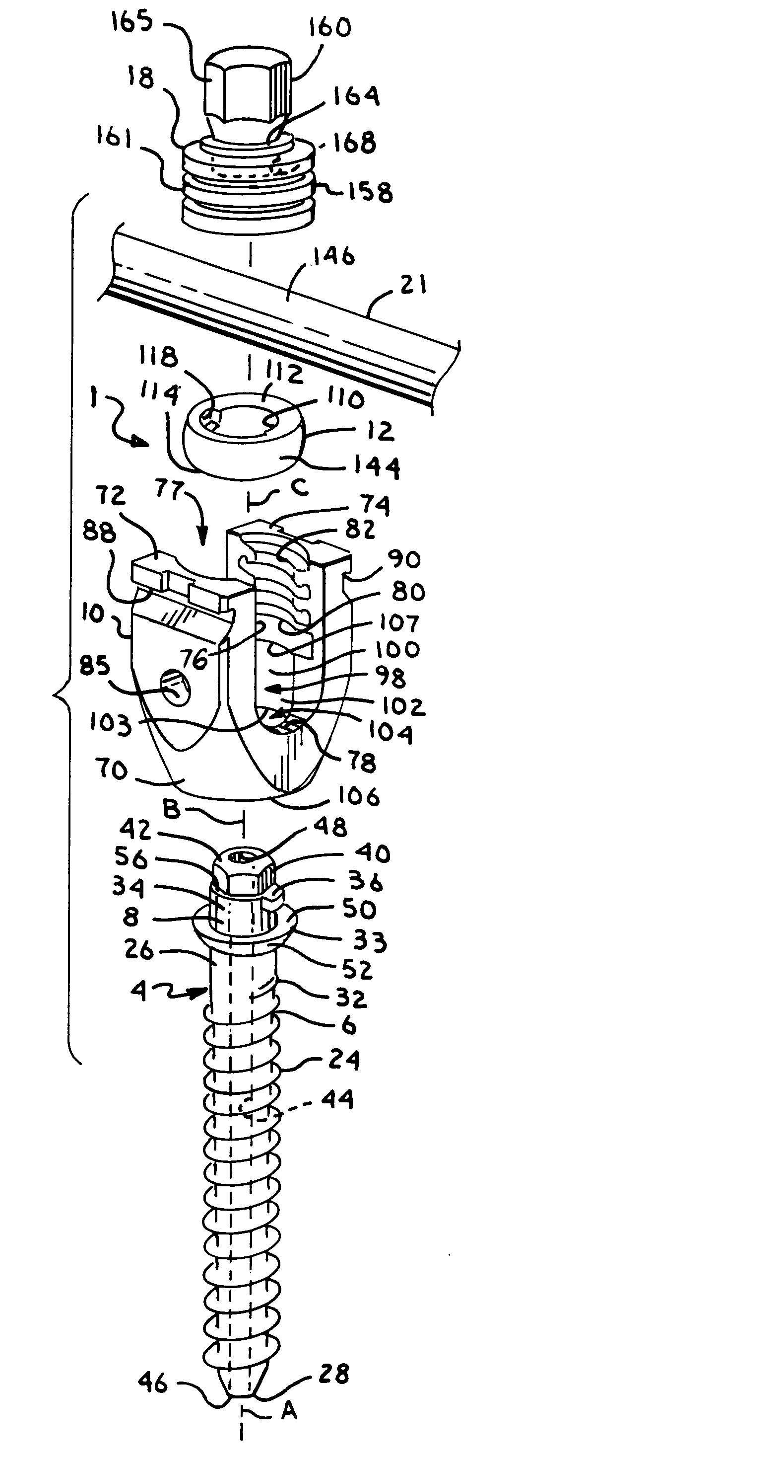
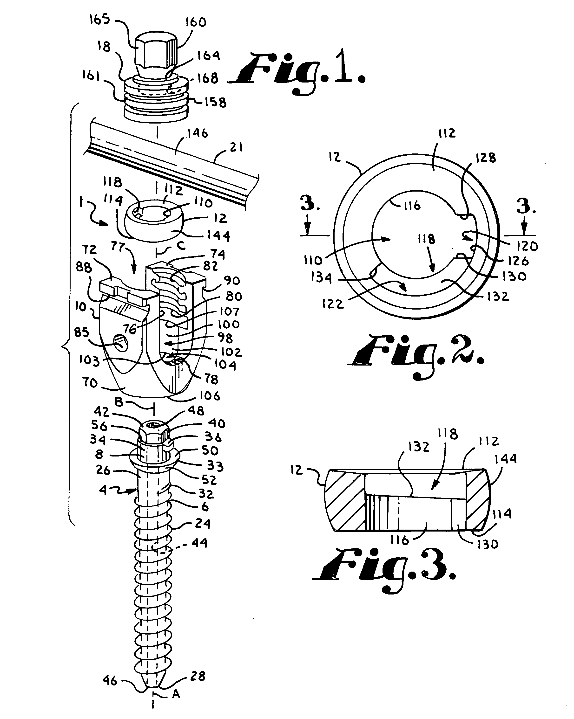
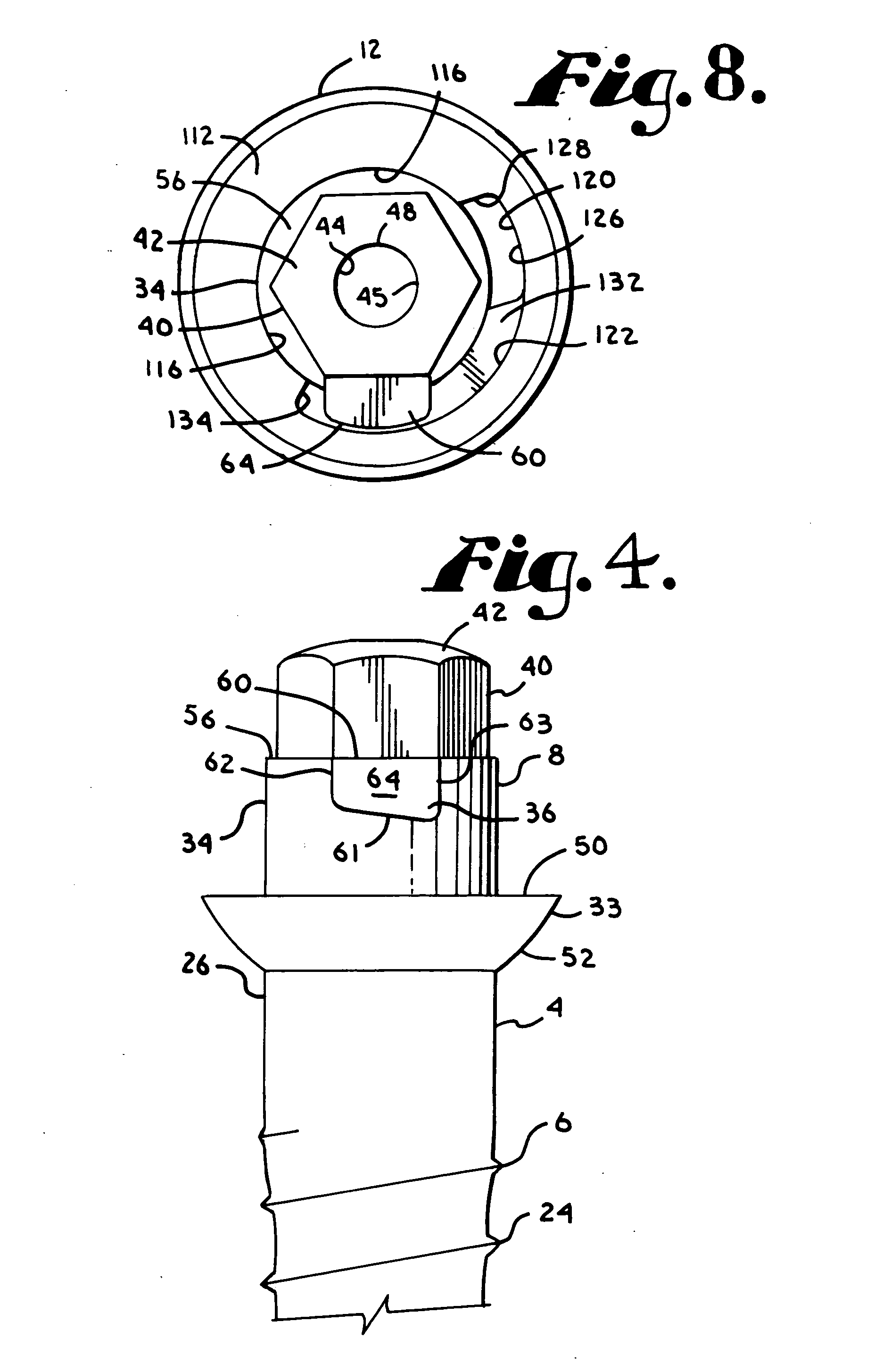
[0029]As required, detailed embodiments of the present invention are disclosed herein; however, it is to be understood that the disclosed embodiments are merely exemplary of the invention, which may be embodied in various forms. Therefore, specific structural and functional details disclosed herein are not to be interpreted as limiting, but merely as a basis for the claims and as a representative basis for teaching one skilled in the art to variously employ the present invention in virtually any appropriately detailed structure. It is also noted that any reference to the words top, bottom, up and down, and the like, in this application refers to the alignment shown in the various drawings, as well as the normal connotations applied to such devices, and is not intended to restrict positioning of bone attachment assemblies of the application and cooperating connecting members in actual use.

[0030]With reference to FIGS. 1-8, the reference number 1 generally represents an embodiment of ...


PUM


Abstract

A polyaxial bone screw assembly includes a threaded shank body having an upper portion with a laterally extending lug and a retainer having an inner cam track for receiving the lug and thus attaching the shank upper portion to the retainer within a receiver. The retainer may be a closed or open ring. The receiver has a cavity and a U-shaped cradle defining a channel for receiving a longitudinal connecting member such as a spinal fixation rod. The retainer has an external surface that mates with an internal surface of the receiver, providing a ball joint.

Description

CROSS REFERENCE TO RELATED APPLICATIONS[0001]This application claims the benefit of U.S. Provisional Application No. 60 / 881,641 filed Jan. 22, 2007 and incorporated by reference herein. This application is also a continuation-in-part of U.S. patent application Ser. No. 10 / 818,554, filed Apr. 5, 2004 which is a continuation of U.S. patent application Ser. No. 10 / 464,633, filed Jun. 18, 2003, now U.S. Pat. No. 6,716,214. U.S. patent application Ser. No. 10 / 818,554 is also a continuation-in-part of U.S. patent application Ser. No. 10 / 651,003, filed Aug. 28, 2003.BACKGROUND OF THE INVENTION[0002]The present invention is directed to polyaxial bone screws for use in bone surgery, particularly spinal surgery. Such screws have a receiver or head that can swivel about a shank of the bone screw, allowing the receiver to be positioned in any of a number of angular configurations relative to the shank.[0003]Many spinal surgery procedures require securing various implants to bone and especially ...

Claims


Application Information

Patent Timeline
IPC IPC(8): A61B17/56
CPCA61B17/7037A61B17/7032
Inventor JACKSON, ROGER P.
Owner JACKSON
Why Eureka
Try Eureka