Miniature garbage incinerator

a technology of incinerators and waste of energy, applied in the direction of capillary burners, combustion types, lighting and heating apparatus, etc., can solve the problems of large waste of energy in the incinerator, and achieve the effect of effectively burning up wastes

Inactive Publication Date: 2002-07-30
CHEN YING TSUNG
View PDF7 Cites 11 Cited by
  • Summary
  • Abstract
  • Description
  • Claims
  • Application Information

AI Technical Summary

Benefits of technology

The present invention has a main object to provide a miniature garbage incinerator which uses helical air current to build up a whirlpool heat circulation inside the incinerator in order to effectively burn up the wastes and synchronously dry up the filthy mud into ashes.
According, the miniature garbage incinerator of the present invention comprises a base, a cover on the top of the base, a pot shaped furnace disposed in the center of the base to define a flame circulation space therearound, a helical pipe communicating to the bottom of the base and a fire source for supplying whirlpool flame into the flame circulation space to burn the wastes and filthy mud inside the furnace, a motor on the central top of the cover for actuating a rotatable rods in the center of the incinerator having a length reached the bottom of the pot shaped furnace, a transverse rod across the cover having a bearing at center to wrap the rotatable rods, a plurality of stirring rod spacedly and perpendicularly connected the lower portion of the rotatable rods, a heat revolving pipe including a blower connected between the cover and the base for leading the heat from the cover back into the base, an inlet at a lateral side of the cover including a spiral propeller tube for feeding the garbage and filthy mud into the furnace, a chimney communicated with the flame circulation space for exhausting the smoke out of the flame circulation space, an ashes collector at a lateral side of the base having spiral propeller tube connected to the furnace for collecting the ashes from the furnace, a pressure adjustment valve in a top of the cover and a pair of guide plate on the lateral sides of the base for protecting the blower and the ashes collector. The garbage incinerator can be used individually or combined with a filthy mud furnace and a heat stove in order to increase the capacity of the incinerator.

Problems solved by technology

However, this type of garbage incinerator wastes a great deal of energy and would not completely dry up the mud but causes environmental contaminant.

Method used


Image

  • Miniature garbage incinerator
  • Miniature garbage incinerator
  • Miniature garbage incinerator

Examples


Embodiment Construction

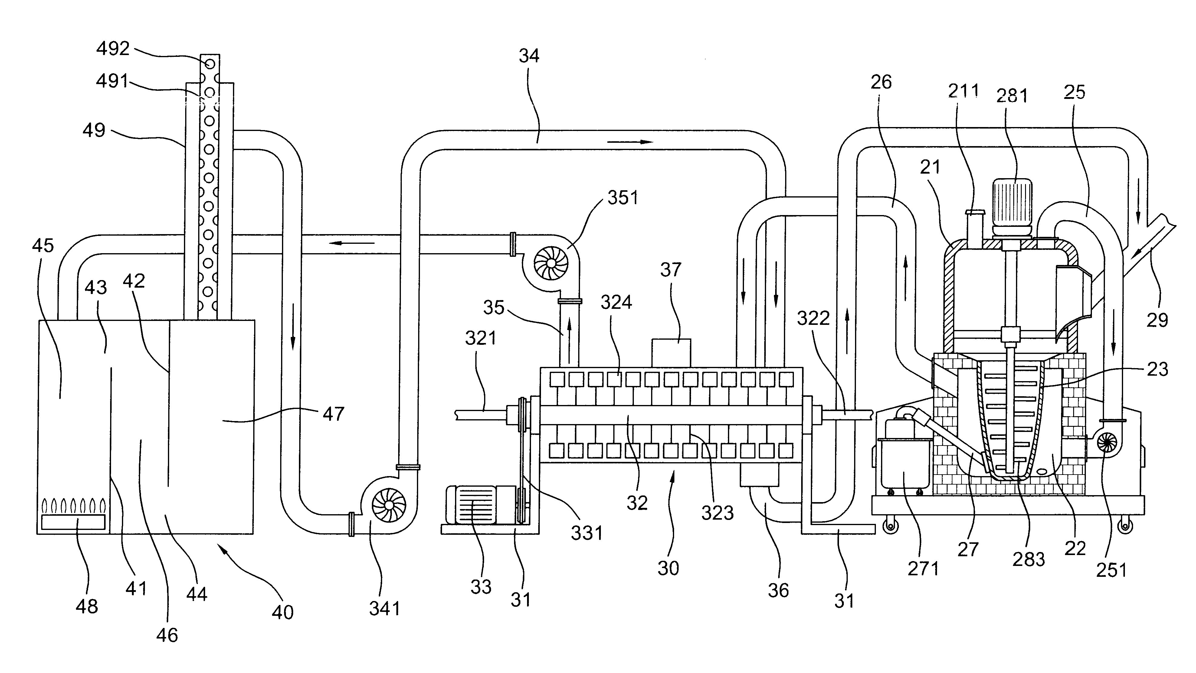
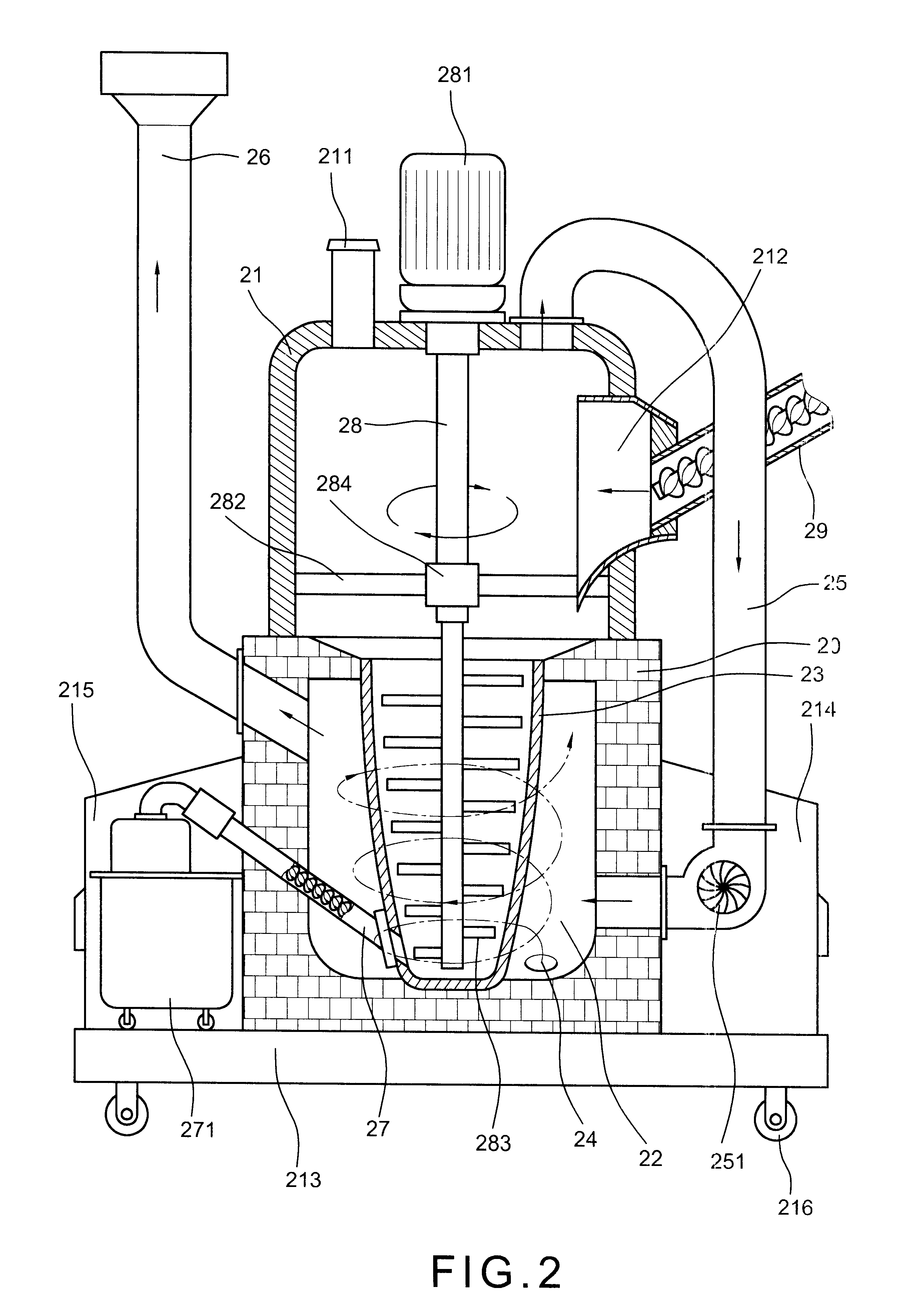
With reference to FIGS. 2, 5 and 6 of the drawings, the miniature garbage incinerator of the present invention comprises a base 20, a cover on the top of the base 20, a pot shaped furnace 23 at the center of the base to define an air revolving space 22 therearound, a helical pipe 24 connected between the air revolving space 22 and a heat source (not shown) under the furnace 23 (as shown in FIG. 6) for providing the whirlpool flame into the air revolving space 22 and surrounding the furnace 23, a heat revolving pipe 25 including a blower 251 connected to a lower lateral wall of the base 20 and a top of the cover 21 for leading the heat from the cover 21 back to the air revolving space 22, a chimney 26 extended upward from an upper lateral wall of the base 20 communicating to the air revolving space 22, a spiral propeller tube 27 having one end connected to the lower portion of the furnace 23 and the other end connected to an ashes collector 271 outside the base 20 for collecting the ...


PUM


Abstract

A miniature garbage incinerator includes a base, a cover on the base, a pot shaped furnace at the center of the base to define an revolving space therearound, a helical pipe connected to the air revolving space and heat source in the bottom of the base for providing whirlpool flame around the furnace, a motor on the central top of the cover to actuate a stirring rod inside the incinerator, an inlet including a spiral propeller tube in a side wall of the cover for feeding the garbage and filthy mud into the furnace, a heat revolving pipe including a blower connected between a top of the cover and a lateral wall of the base, a chimney connected to a lateral wall opposite to the heat revolving pipe, a pressure adjustment valve on a top of the cover and an ashes collector under the chimney connected to the bottom of the furnace through an ashes spiral propeller tube. The miniature garbage incinerator can be used individually or combined with a filthy mud furnace and a heat stove.

Description

The present invention relates to incinerator and more particularly to a miniature garbage incinerator which can dispose the wastes and filthy mud synchronously.Typical miniature garbage incinerator (as shown in FIG. 1) comprises a main incinerator 10 and a filthy mud furnace 16. The main incinerator 10 has a motor 13 for controlling a sliding door 11 where is the inlet of the incinerator 10, a burner in the lower portion 12, a guide pipe 14 at a top communicating to the filthy mud furnace 16 which has an inlet 18 for the entrance of the filthy mud into the furnace 16 and a motor 17 operating a shaft 19 for stirring the filthy mud inside the furnace to be quickly dried up. When ignite the burner, the fire burns the wastes inside the main incinerator 10 and the superfluous heat enter into the furnace 16 via the guide pipe 14 to heat the filthy mud which under the stirring of the shaft 19 will be dried up into ashes. However, this type of garbage incinerator wastes a great deal of ener...

Claims


Application Information

Patent Timeline
Patent Type & Authority Patents(United States)
IPC IPC(8): F23G5/38F23G5/00F23G5/24F23G5/28F23G5/04F23G5/02
CPCF23G5/006F23G5/008F23G5/04F23G5/28F23G5/38F23G2203/70F23G2209/12
Inventor CHEN, YING-TSUNG
Owner CHEN YING TSUNG
Why Eureka
Try Eureka