Quick engine startup system and method

a technology of engine startup and engine control, which is applied in the direction of electric control, machines/engines, mechanical equipment, etc., can solve the problems of increasing requiring greater power output from the engine, and requiring significant power output for the engine, so as to improve the time of recuperation, reduce the depth of speed reduction, and improve the response to increased power demands

Active Publication Date: 2009-09-03
GE GLOBAL SOURCING LLC
View PDF27 Cites 26 Cited by
  • Summary
  • Abstract
  • Description
  • Claims
  • Application Information

AI Technical Summary

Benefits of technology

[0006]The present invention provides a novel engine system and method of controlling such a system designed to respond to such needs. The invention may be applied in a wide range of settings, such as for driving locomotive engines, ship engines, engines of other work and transport vehicles, generator engines, and so forth. The invention allows for improved response to increased power demands, while reducing the depth of speed reductions and improving the time of recuperating from such speed reductions. The invention also allows for improved control of the fuel-to-air mixture, reducing emissions and providing more efficient combustion during a transition period in response to increased power output demands.
[0007]In accordance with certain aspects of the technique, a storage vessel is provided for storing compressed air that may be injected into the engine in response to increased power demands. The storage vessel may be charged by a compressor that is used to provide air to engine during normal operation. Valving may be provided that allows for the stored air to remain isolated during normal engine operation. When particular power demands are made on the engine, then, the valving may be actuated to inject the compressed air into the engine to decrease the fuel-to-air ratio as fuel injection rates are increased. Additional valving may allow for discharging of air from the compressor during such operation, to avoid surge.

Problems solved by technology

One difficulty that arises in such applications involves the need for significant power output for the engine from either a cold start or in response to changing conditions, such as increased power demand.
In the case of locomotives and other transport vehicles, when steeper grades are encountered, additional torque or tractive effort is required to maintain the speed of a vehicle or train, requiring greater power output from the engine.
Conventional engine controls may not appropriately respond to such higher power output demands.
For example, because higher power is required of the engine, the engine controls will generally cause greater amounts of fuel to be injected into the engine.
The fuel increase may not be immediately matched, however, by proportionate increases in air supplied to the engine.
As a result, the fuel-air mixture may become too rich during the resulting transitional period, causing a significant reduction or droop in engine speed, which is only recuperated quite slowly.
Such speed droops are not generally desirable.
Similarly, the richer mixture supplied to the engine can exceed design limits, resulting in inefficient combustion, and the discharge of smoke or particulate from the engine exhaust.

Method used


Image

  • Quick engine startup system and method
  • Quick engine startup system and method
  • Quick engine startup system and method

Examples


Embodiment Construction

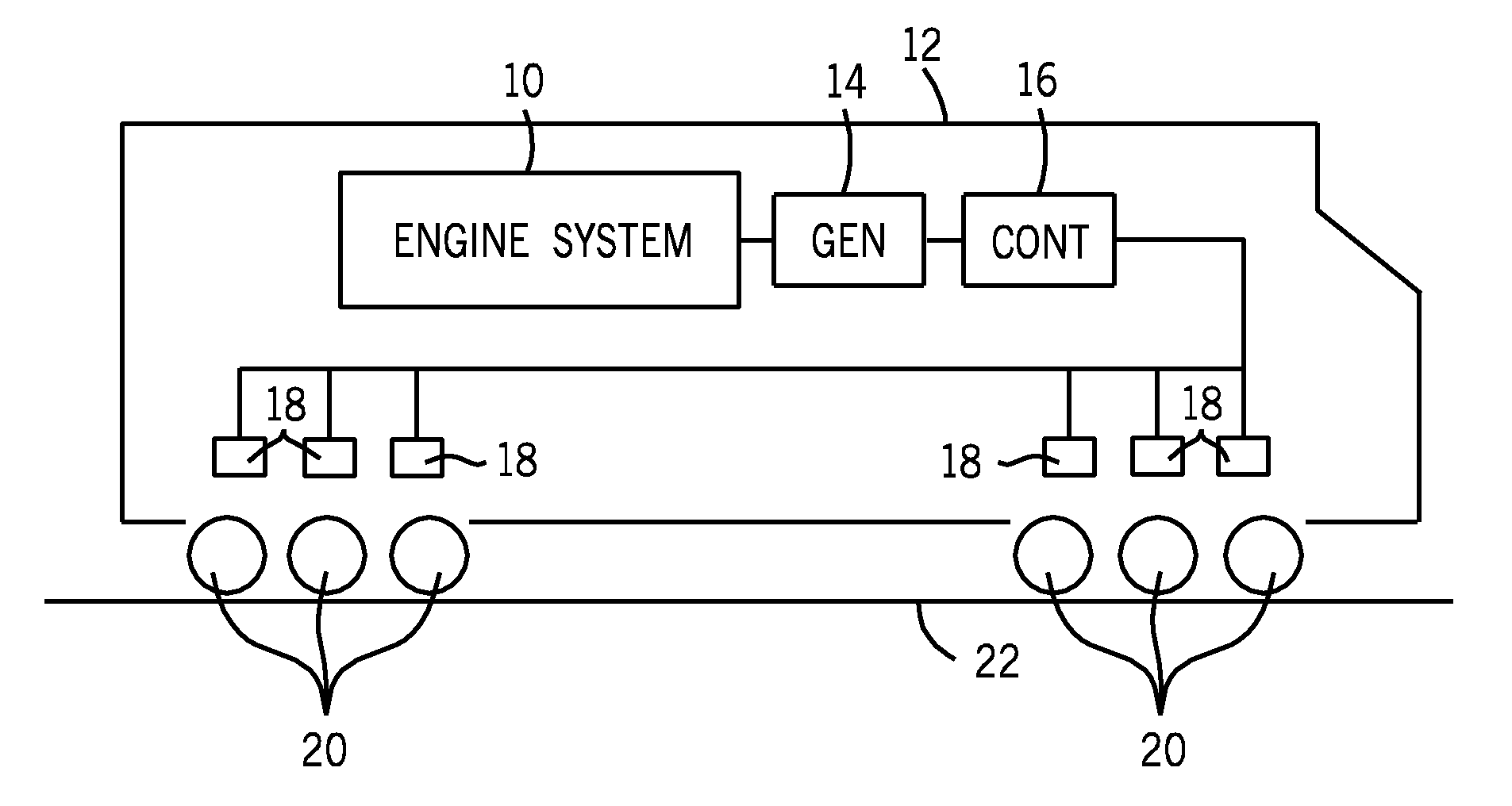
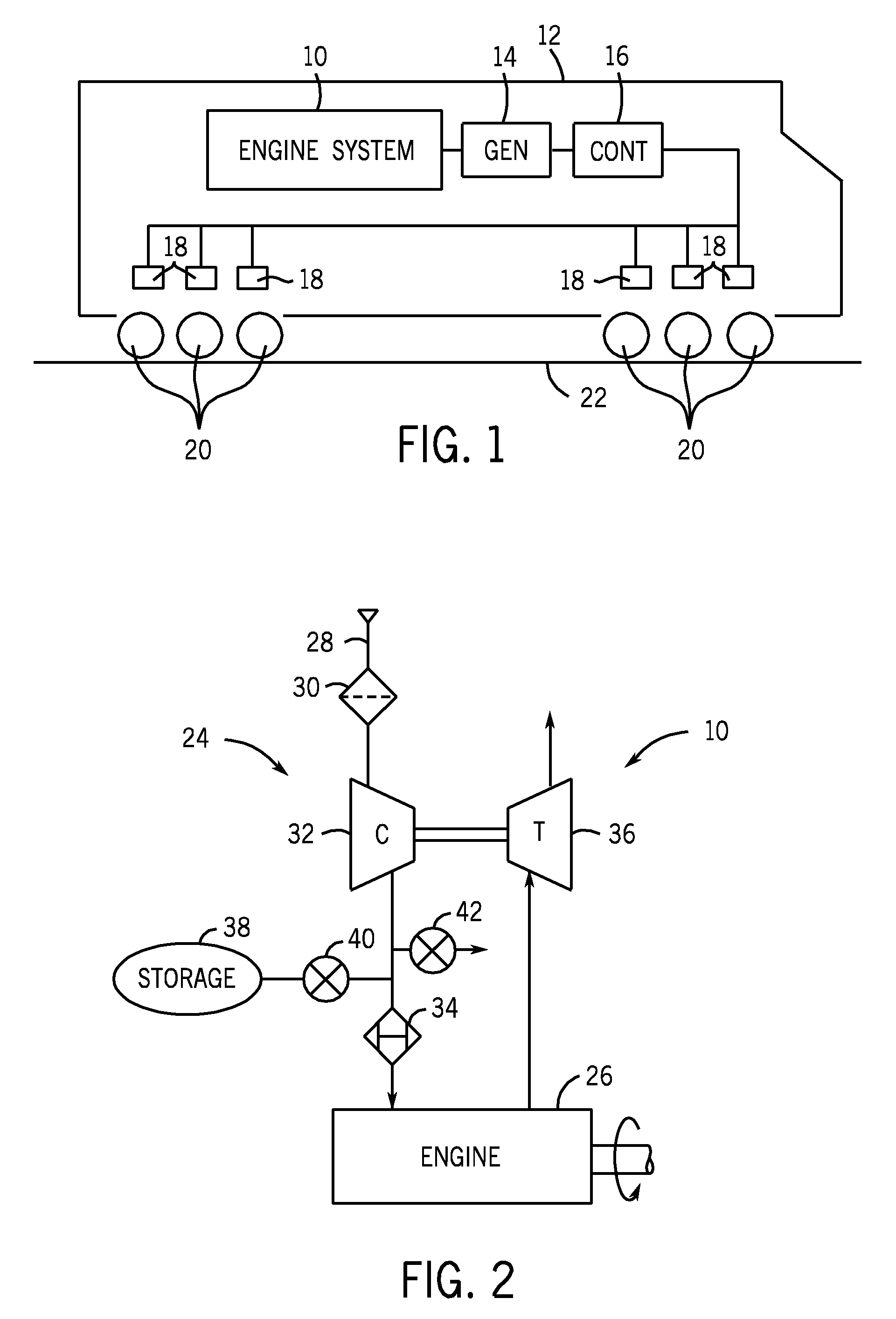
[0014]Turning now to the drawings, referring first to FIG. 1, an engine system 10 is illustrated in an exemplary embodiment. Specifically, engine system 10 is provided in a railway locomotive 12. The engine system drives a generator 14 that produces electrical power that may be stored and is ultimately applied for driving the locomotive to pull railway cars coupled to it. An electrical control and distribution system 16 will typically be provided for controlling operation of the electrical components, including the generator, and electric motors 18 coupled to wheel-axial sets 20. For the present purposes, controller 16 may also be considered to control operation of engine system 10, although, as will be appreciated by those skilled in the art, the engine system will typically have its own dedicated engine controller, or several controllers that work in unison to regulate operation of the engine to regulate tractive effort output by the wheel-axial sets, and so-forth. Ultimately, pow...


PUM


Abstract

A technique is provided for improved response of internal combustion engines to increased load demands. The engine is equipped with an air storage tank that stores compressed air. The air may be stored at an elevated pressure (e.g., manifold air pressure) during normal full load operation of the engine. Valving maintains the compressed air isolated during normal operation. During transitory periods of higher power output demand, the compressed air is directed to the engine, and output of a turbo-driven compressor can be vented to avoid surge. The technique allows for quicker reaction to load demands, and improved combustion during transitory periods, and reduced particulate and smoke emissions.

Description

BACKGROUND[0001]The present invention relates generally to internal combustion engines and engine controls, and particularly to large engines used in demanding applications, such as work vehicles, locomotives, gensets and so forth.[0002]Many control approaches and schemes have been devised for internal combustion engines, particularly for large, powerful diesel engines and engines running on other fuels. In railway locomotives, for example, such engines serve to generate electrical power which is transmitted to wheel-axle units. The wheel-axle units include electric motors that are driven to provide the desired tractive effort to move the locomotive and any railway cars coupled to it along railways. Other applications for large, powerful engines include ships, tractors, on and off-road trucks, electrical power generators, and so-forth.[0003]One difficulty that arises in such applications involves the need for significant power output for the engine from either a cold start or in res...

Claims


Application Information

Patent Timeline
Patent Type & Authority Applications(United States)
IPC IPC(8): F02D41/06
CPCF02B21/00F02B33/44F02B37/00Y02T10/42F02D41/0002F02M23/06Y02T10/144F02D23/02Y02T10/12Y02T10/40
Inventor GOKHALE, MANOJ PRAKASHKUMAR, YOGESH
Owner GE GLOBAL SOURCING LLC
Why Eureka
Try Eureka