Portable fire pit system

a fire pit and portable technology, applied in the field of portable fire pit systems, can solve the problems of inefficiency of fuel itself, insufficient utilization of fire pit space, and many fire pits without ventilation, and achieve the effect of efficient burning of fuel

Inactive Publication Date: 2012-08-02
SUMMIT WOOD INDS
View PDF7 Cites 26 Cited by
  • Summary
  • Abstract
  • Description
  • Claims
  • Application Information

AI Technical Summary

Benefits of technology

[0007]The present invention provides a fire pit to be used in conjunction with particularly sized fuel blocks, and align these fuel blocks in a square-shaped configuration around ventilation holes provided through the base of the fire pit. The base is formed from a plate having a plurality of alignment flanges extending upwardly therefrom. The alignment flanges provide a positioning and alignment brace for the fuel blocks, which are fitted into an abutting relationship with the alignment flanges and one another while on the plate. After the first layer of fuel blocks is formed, multiple horizontal layers of fuel blocks may be disposed on one another to provide a sufficient vertical length of fuel for a fire. It is a primary feature of the invention that the ventilation holes are disposed generally in the center of the base and align with an inner chimney or air shaft formed by the positioning of the fuel blocks. This chimney or air shaft is formed by the fuel blocks over the ventilation holes to allow the fire to burn from the chimney outwardly through the blocks and thereby provide an efficient burning of the fuel.

Problems solved by technology

Namely, the placement of wood or fuel is typically haphazard and therefore the space inside the fire pit is not fully utilized, and the fuel itself burns inefficiency.
Furthermore, many fire pits do not include ventilation beyond a simple bowl-like structure which only allows air to be supplied from above the fire.

Method used


Image

  • Portable fire pit system
  • Portable fire pit system
  • Portable fire pit system

Examples


Embodiment Construction

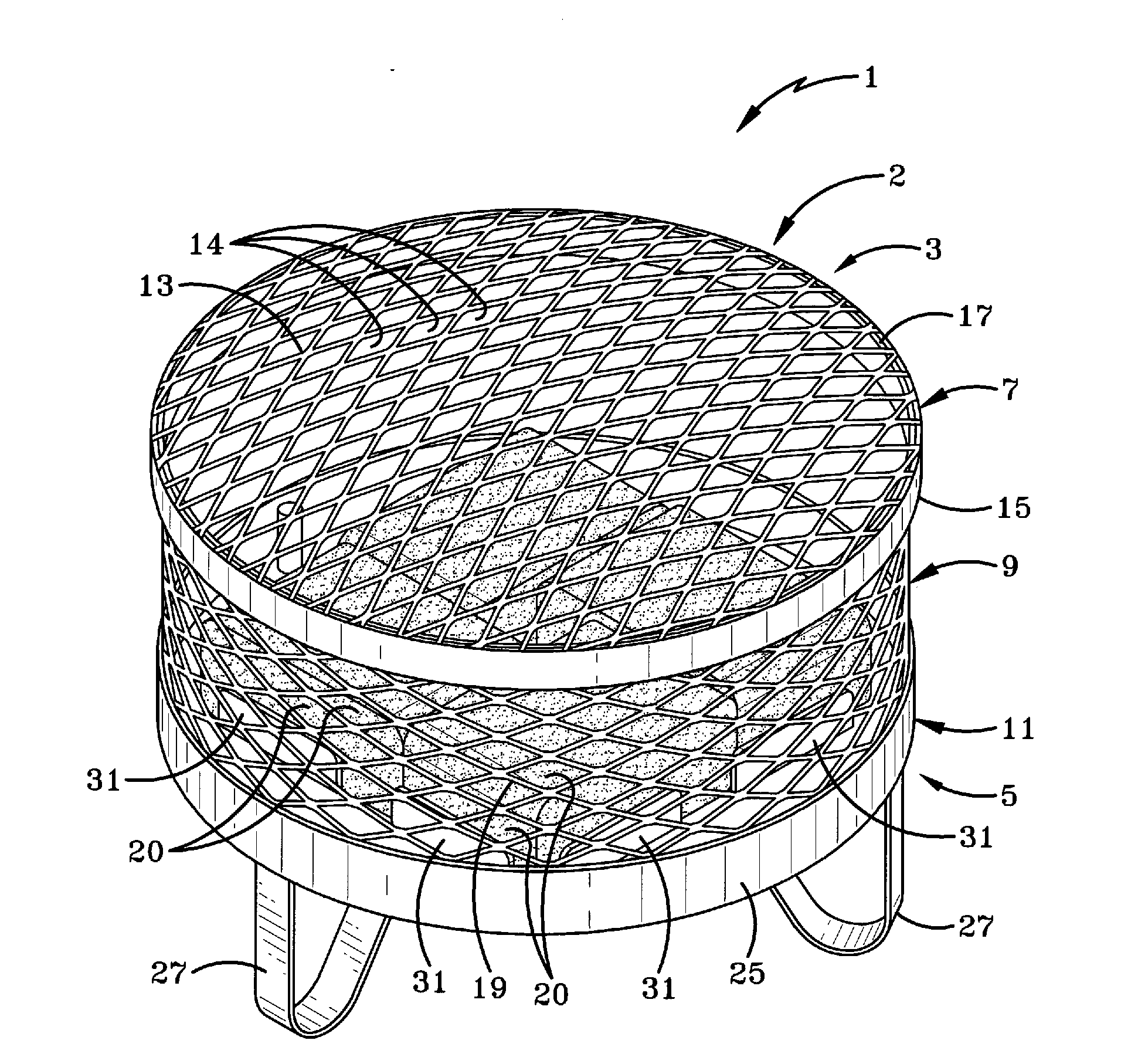
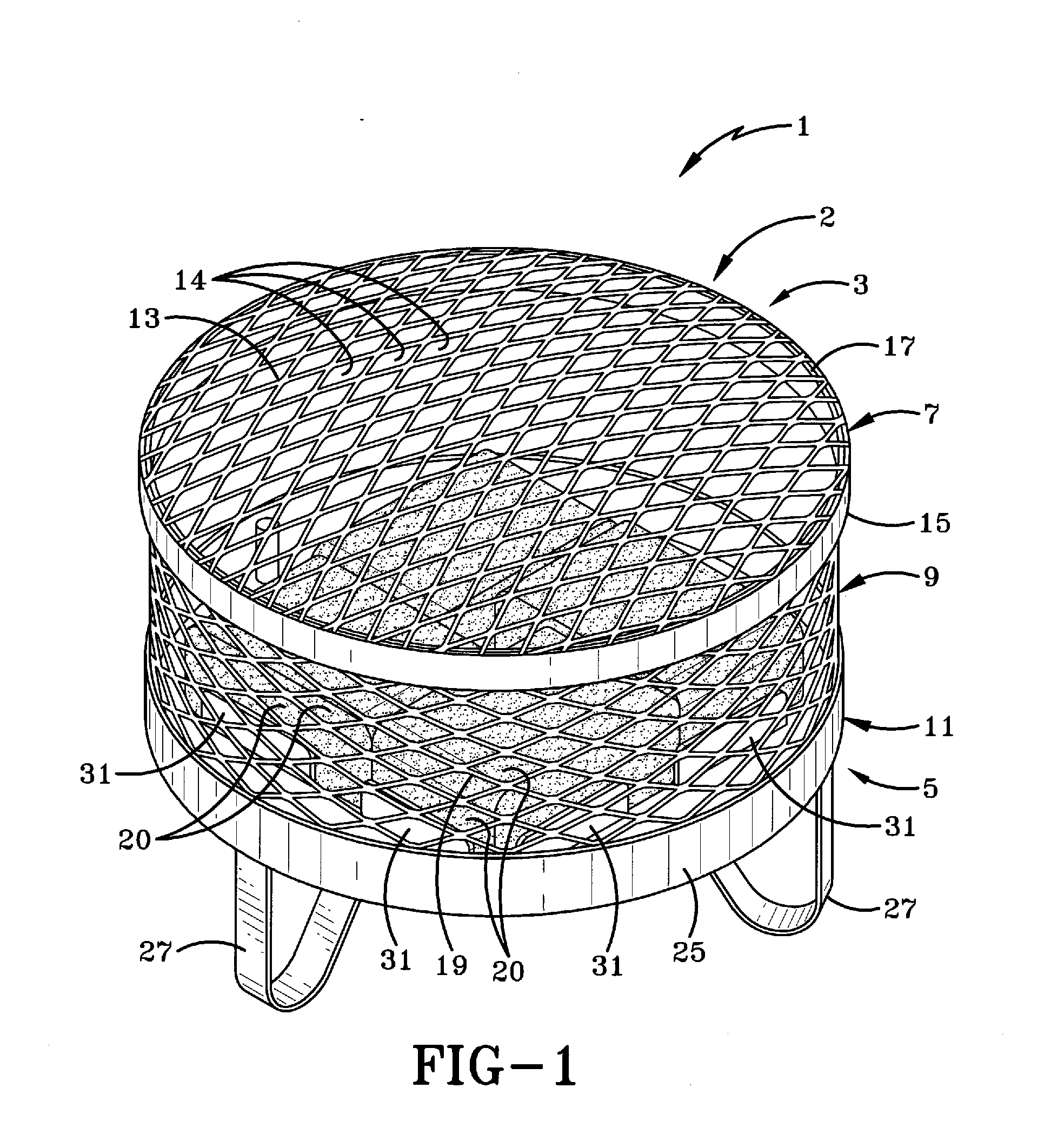
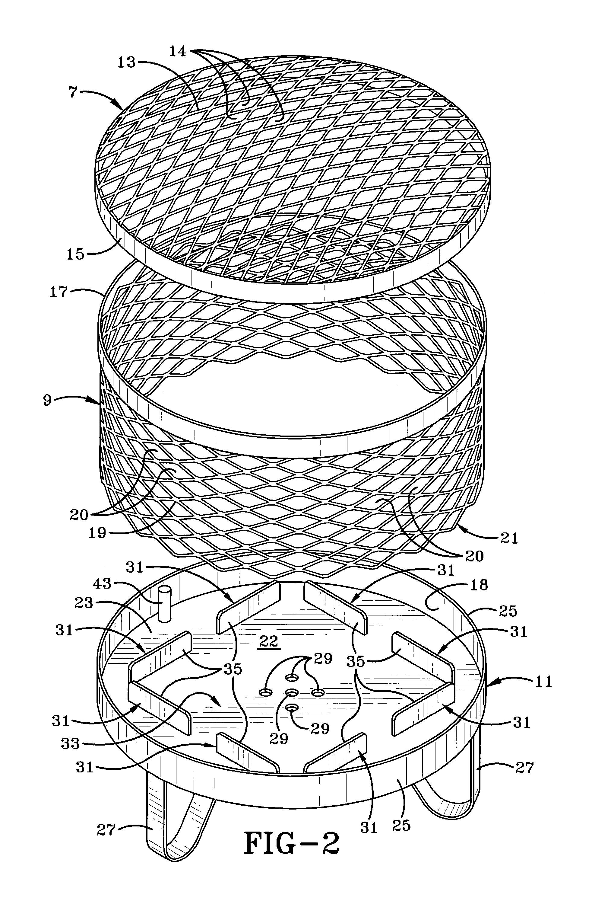
[0021]The portable fire pit system of the present invention is shown in FIGS. 1-11 and is indicated generally at 1. As shown in FIGS. 1 and 2, fire pit system 1 includes a fire pit 2 which extends generally from an upper end 3 to a lower end 5 and includes a lid 7, a spark guard 9, and a base 11. Lid 7 includes a wire mesh portion 13 which defines a plurality of openings 14 and extends from an annular ring 15. Annular ring 15 is sized to removably and snuggly fit around an annular ring 17 having a slightly smaller diameter and disposed on spark guard 9. Spark guard 9 further includes a wire mesh portion 19 extending from annular ring 17 to a lower end 21, and is formed in a generally cylindrical overall shape. Wire mesh portion 19 defines a plurality of openings 20 for allowing air to pass therethrough and to prevent cinders or floating ash from escaping and starting a fire outside the pit.

[0022]Referring to FIGS. 1-3, base 11 includes a plate 23 having an upper surface 22, a lower ...


PUM


Abstract

The present invention provides a portable fire pit to be used in conjunction with particularly sized fuel blocks, whereby these fuel blocks are manually positioned in a square-shaped configuration around ventilation holds provided through the base of the fire pit. Alignment flanges on the base provide a positioning and alignment brace structure for the fuel blocks, which are fitted into an abutting relationship with the alignment flanges and one another on the base. The ventilation holes are formed to align with an inner chimney formed by the positioning of the fuel blocks. This chimney is formed over the ventilation holes to allow the fire to burn from the chimney outwardly through the blocks and thereby provide an efficient burning of the fuel.

Description

CROSS-REFERENCE TO RELATED APPLICATION[0001]This application claims priority from U.S. Provisional Application Ser. No. 61 / 437,064, filed Jan. 28, 2011, the disclosure of which is incorporated herein by reference.BACKGROUND OF THE INVENTION[0002]1. Technical Field[0003]The present invention relates generally to fire pits. More particularly, the present invention relates to an outdoor backyard fire pit configured to receive fuel blocks having a particular shape. Specifically, the present invention relates to such a fire pit which is configured to receive and hold fuel blocks in a desired placement around a vent opening to allow an efficient burning of the fuel.[0004]2. Background Information[0005]The general concept of a fire pit can physically vary from a pit dug into the ground to an elaborate gas burning compilation of stone, brick, and metal. The common feature of fire pits is that they are designed to contain a fire and prevent it from spreading. Pre-made fire pits are the most ...

Claims


Application Information

Patent Timeline
Patent Type & Authority Applications(United States)
IPC IPC(8): F24B1/182
CPCF24B3/00
Inventor MILLER, GARY
Owner SUMMIT WOOD INDS
Why Eureka
Try Eureka