Thrust plate assembly

a technology of thrust plate and assembly plate, which is applied in the direction of mechanical actuator clutches, manufacturing tools, mechanical apparatus, etc., can solve the problems of generating a relative vibration between the thrust adjustment device and the detection portion of the flywheel, reducing the action and reducing the effect of the wear adjustment device. , to achieve the effect of simple and reliable operation

Inactive Publication Date: 2002-07-30
ZF FRIEDRICHSHAFEN AG
View PDF6 Cites 5 Cited by
  • Summary
  • Abstract
  • Description
  • Claims
  • Application Information

AI Technical Summary

Benefits of technology

An essential characteristic of the thrust plate assembly according to the present invention is that the detection element alone blocks of the wear adjustment device for preventing an unwanted relative adjusting movement , i.e., a force loop or force feedback is provided within the detection element. The wear adjustment elements and the respective detection element accordingly form a self-enclosed unit with respect to forces and there is low risk that individual components will vibrate against one another due to the relatively small masses. Relative movements of the wear adjustment elements and / or the detection element, for example, relative to the pressure plate, do not produce an unwanted wear adjustment because the detection element is not fixedly tied to the pressure plate, as is the case in the prior art. Rather, the detection element according to the present invention is supported at the wear adjustment device.
According to a preferred embodiment of the present invention, the first application area and the second application area of the detection element are pretensioned toward one another. To provide the above-mentioned function of generating a force feedback in a simple manner via the detection element, the detection element may comprise a spring clamp element having first and second leg areas in which the first application area is arranged on the first leg area and the second application area is arranged on the second leg area. Furthermore, the detection portion of the detection element may be provided at the first leg area.
To introduce the force of the energy accumulator in a simple and reliably operating manner, the first adjustment element is supported at a component of the energy accumulator and acts on the second adjustment element. It is preferably provided that the first adjustment element is acted upon by the first application area, i.e., by the leg area of the detection element at which the detection portion is also provided.

Problems solved by technology

When wear occurs, the pressure plate moves toward the flywheel causing the detection portion to strike the flywheel.
As a result, the leaf spring element is somewhat relaxed, thereby diminishing its action upon the wear adjustment device.
However, a fundamental problem in the operation of systems of this type is that occurring vibrations or shaking movements can generate a relative vibration between the wear adjustment device and, for example, the pressure plate.
It must then be ensured in the disengaged state through the action of the leaf spring element that these vibrations cannot cause the wear adjustment device to be lifted from the pressure plate, which could result in spontaneous execution of a wear adjusting movement.

Method used


Image

  • Thrust plate assembly
  • Thrust plate assembly
  • Thrust plate assembly

Examples


Embodiment Construction

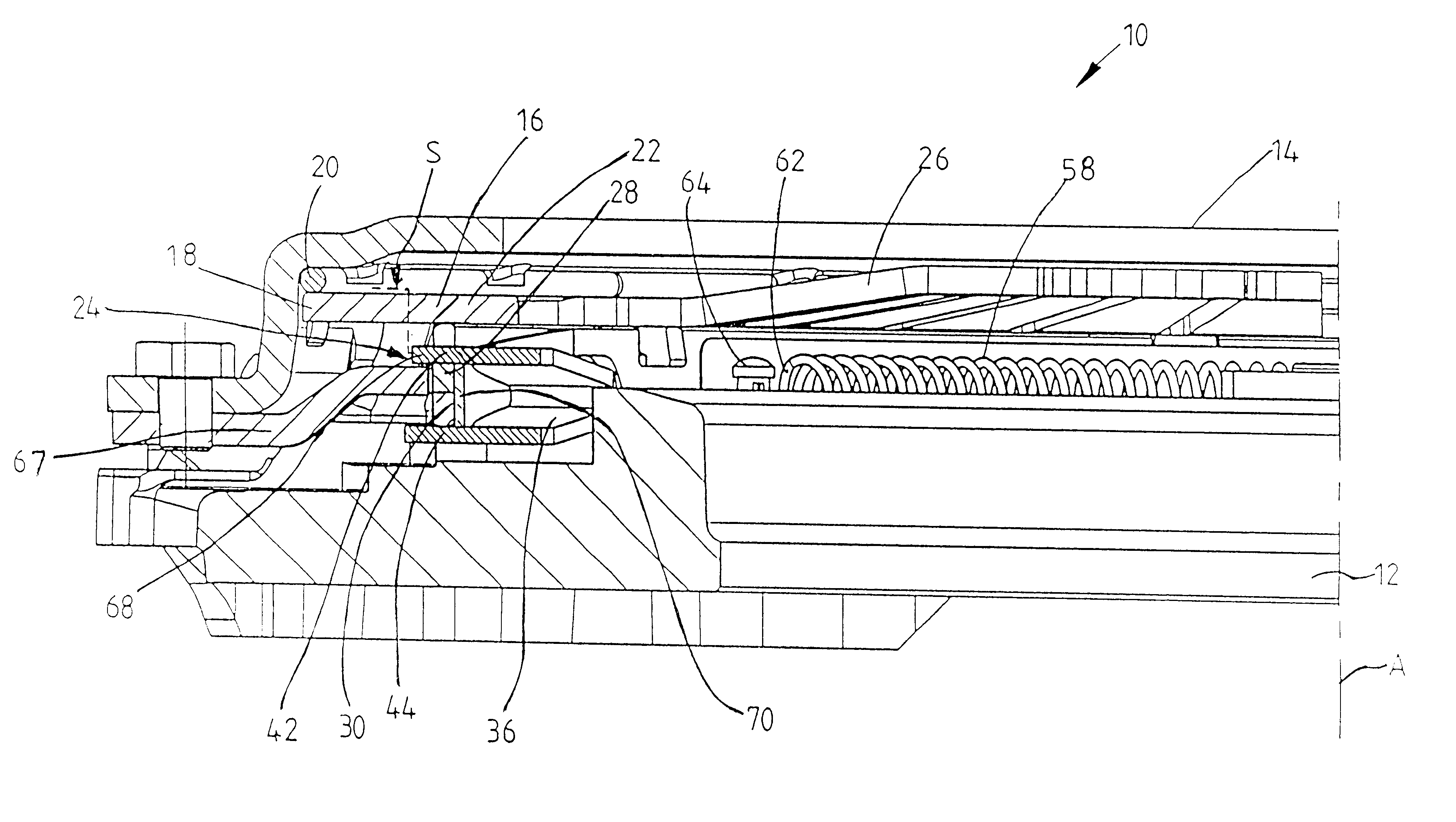
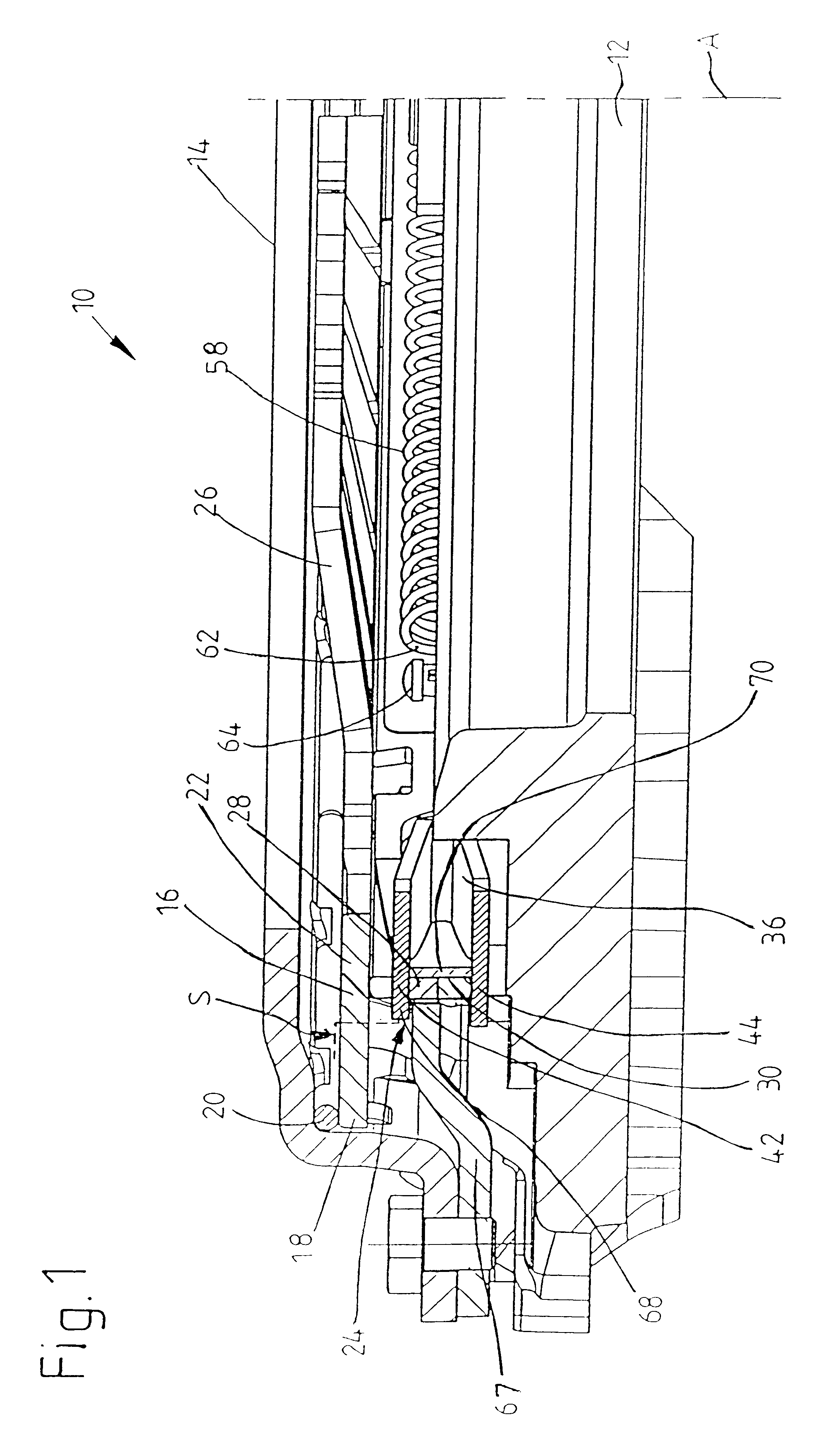
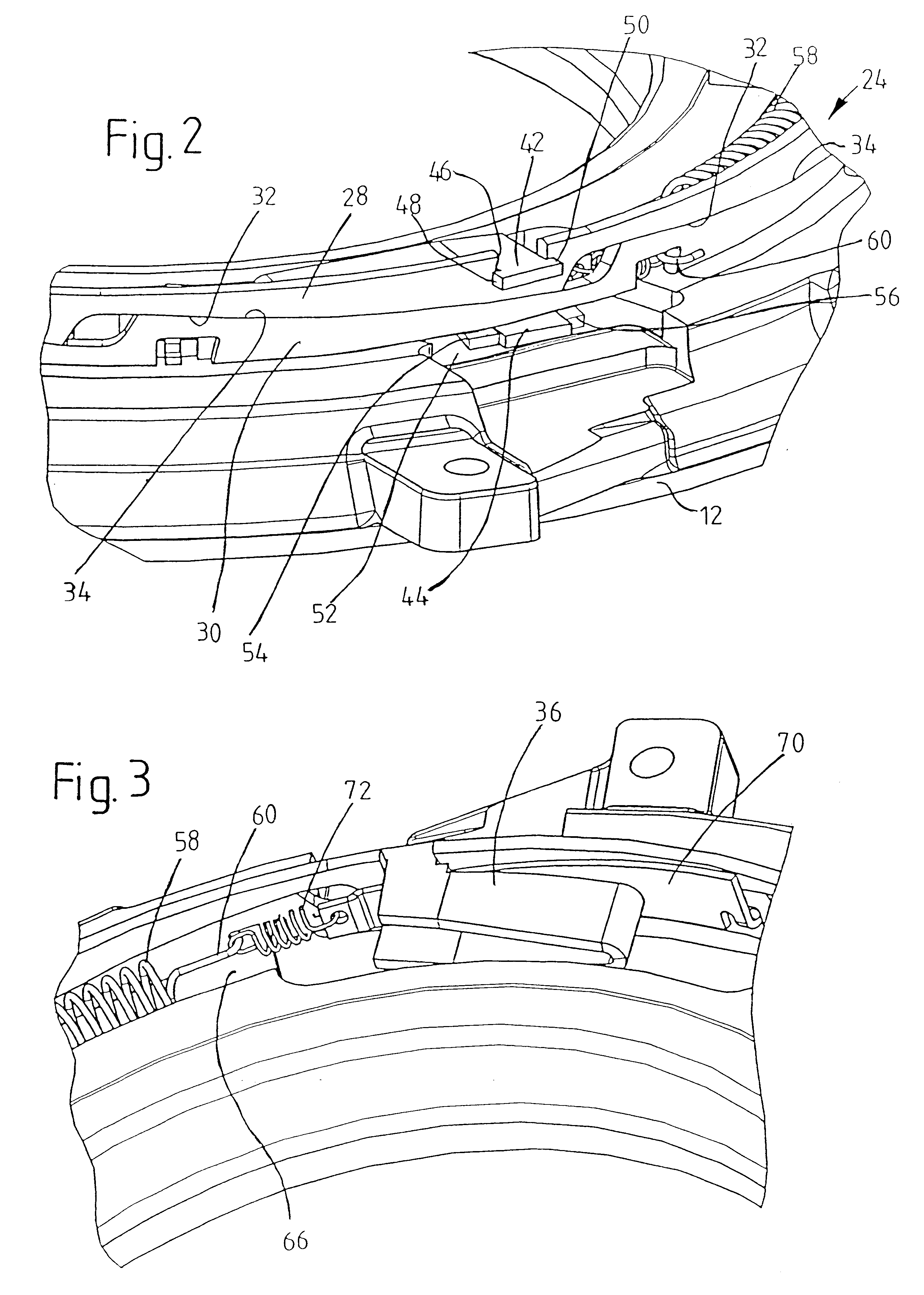
FIGS. 1 to 6 show a thrust plate assembly 10 according to the present invention. The thrust plate assembly 10 includes a pressure plate 12 arranged in a housing 14 and connected with the housing 14 via connecting elements (e.g., by tangential leaf springs or the like), not shown, so that the pressure plate 12 is fixed with respect to rotation relative to the housing 14, but axially movable relative to the housing 14. The housing 14 fixedly connectable, in a manner known per se, with a flywheel of a friction clutch, so that the friction linings of a clutch disk, not shown, may be clamped between the pressure plate 12 and the flywheel.

A diaphragm spring 16 is arranged inside the housing 14 as an energy accumulator. A radial outer area 18 of the diaphragm spring 16 is supported via a supporting ring 20 at the housing 14 and an area 22 of the diaphragm spring 16 located farther radially inward acts on a wear adjustment device 24 to be described in the following. The wear adjustment devi...


PUM

PropertyMeasurementUnit
pressureaaaaaaaaaa
areaaaaaaaaaaa
distanceaaaaaaaaaa

Abstract

A thrust plate assembly for a motor vehicle friction clutch with automatic wear compensation includes a housing which is connectable to a flywheel for rotation jointly with the flywheel about an axis of rotation and a pressure plate arranged in the housing so that the pressure plate is fixed with respect to rotation relative to the housing and axially displaceable relative to the housing. An energy accumulator is supported between the housing and the pressure plate. A wear adjustment device having first and second adjustment elements is arranged in the support path of the energy accumulator. The first and second adjustment elements are pretensioned relative to one another for effecting a relative adjusting movement. A play sensor arrangement arranged for detecting wear includes a detection element which acts upon the wear adjustment device to prevent a relative adjusting movement of the adjustment elements and a detection portion for interacting with a component that moves relative to the pressure plate when wear occurs. The detection element releases the adjustment elements for effecting the relative adjusting movement when wear occurs by the interaction with the component. A stopping element is arranged for stopping the detection element in its position for releasing the adjustment elements.

Description

BACKGROUND OF THE INVENTION1. Field of the InventionThe present invention is directed to a thrust plate assembly for a friction clutch with automatic wear compensation. The thrust plate assembly includes a housing which is connected or connectable to a flywheel for rotation with the flywheel about an axis of rotation, a pressure plate arranged in the housing so that the pressure plate is fixed with respect to rotation relative to the housing and axially displaceable relative to the housing, an energy accumulator having one side supported at the housing and another side supported at the pressure plate, a wear adjustment device having at least two adjustment elements pretensioned relative to one another for carrying out a relative adjusting movement arranged in the support path of the energy accumulator between the energy accumulator and a first component of one of the housing and pressure plate, and at least one play sensor arrangement for detecting wear including a detection element...

Claims


Application Information

Patent Timeline
Patent Type & Authority Patents(United States)
IPC IPC(8): F16D13/58F16D13/75
CPCF16D13/757Y10T29/49904Y10T29/49863
Inventor WEIDINGER, REINHOLD
Owner ZF FRIEDRICHSHAFEN AG
Why Eureka
Try Eureka