Mount for assist grip

a technology of assist grips and mounting brackets, which is applied in the direction of roofs, mechanical equipment, transportation and packaging, etc., to achieve the effects of high rigidity, ease and reliability, and easy flexing

Inactive Publication Date: 2002-08-06
DAIKYONISHIKAWA CORP
View PDF16 Cites 30 Cited by
  • Summary
  • Abstract
  • Description
  • Claims
  • Application Information

AI Technical Summary

Benefits of technology

With the above structure of the invention of Claim 1, since provisional retention of the mount is made by the retention piece, the pair of engaging pieces need only a function of fully retaining the mount. Therefore, if the engaging pieces are set to come into slight or no contact with the edge of the panel opening when inserted into the panel opening, they scarcely experience resistance to insertion but the provisional retention piece exclusively experiences it. Accordingly, the provisional retention piece can be smaller in size than the engaging piece in consideration of its function. Consequently, even if the provisional retention piece of small size has a high rigidity, it is easily flexed as compared with the case of making provisional retention by using the engaging pieces entirely without a dedicated provisional retention piece and provides ease and reliable provisional retention of the mount with a small insertion, resulting in increased working efficiency.
Further, at the full retention of the mount after the provisional retention, the locking member is press-inserted between the pair of engaging pieces so that the engaging pieces are moved apart from each other. The engaging pieces are thus engaged on the edge of the panel opening for the first time. In this case, the provisional retention piece needs only a function of provisionally retaining the mount. Therefore, if the locking member is set to come into slight or no contact with the provisional retention piece when press-inserted between the engaging pieces, the provisional retention piece scarcely experiences resistance to insertion but the engaging pieces exclusively experience it. Accordingly, the engaging piece can be smaller in size by a portion corresponding to the provisional retention piece as compared with the case of using the engaging pieces only without the provisional retention piece. Consequently, even if the engaging piece of small size has a high rigidity, it is easily flexed and provides ease and reliable full retention of the mount with a small insertion, resulting in increased working efficiency.
With the above structure of the invention of Claim 4, the function of fully retaining the mount is added to the provisional retention piece and therefore the mounting strength for the mount can be increased.

Problems solved by technology

Therefore, if the engaging pieces are set to come into slight or no contact with the edge of the panel opening when inserted into the panel opening, they scarcely experience resistance to insertion but the provisional retention piece exclusively experiences it.

Method used


Image

  • Mount for assist grip
  • Mount for assist grip
  • Mount for assist grip

Examples


embodiment 1

(Embodiment 1)

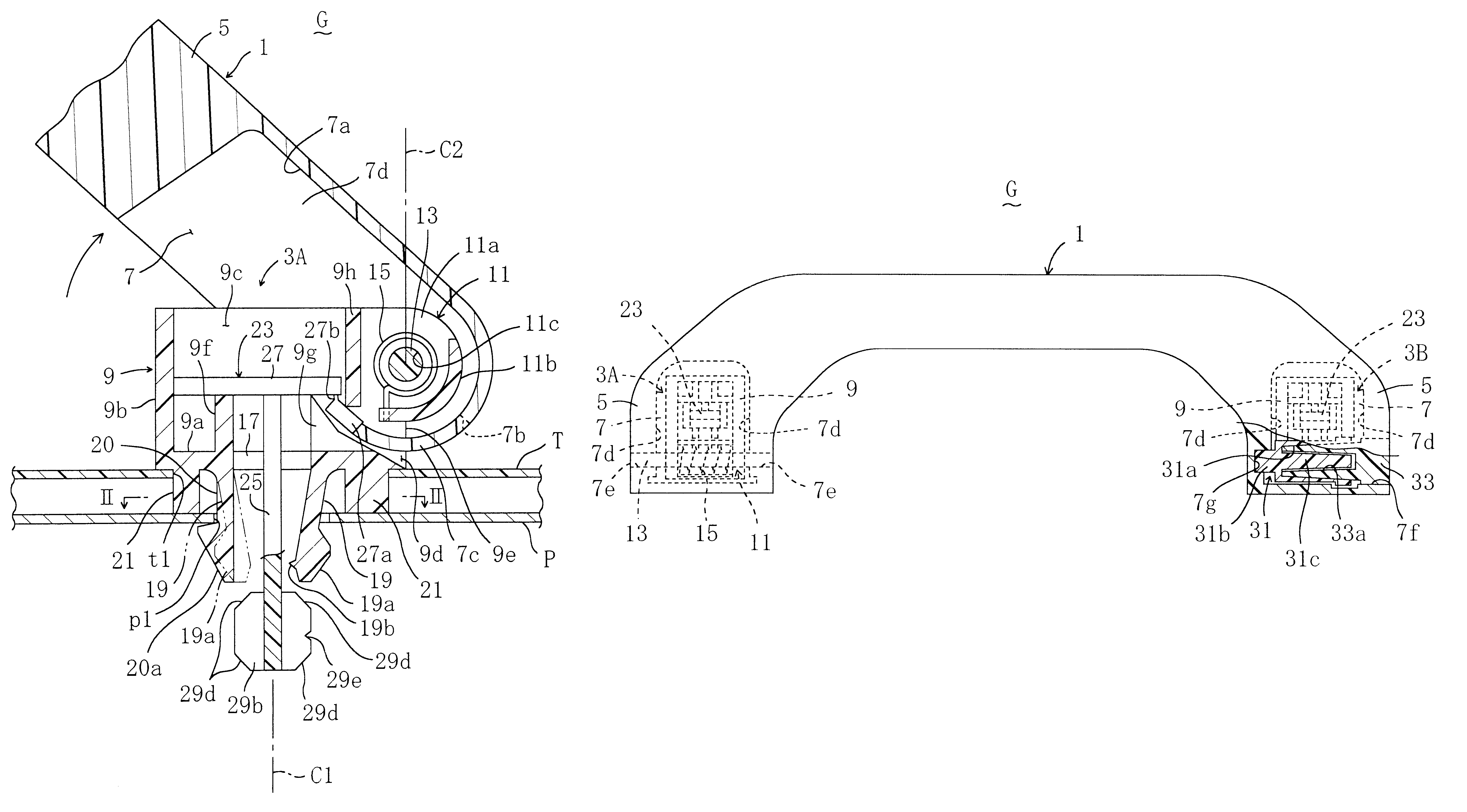
FIGS. 1 to 7 shows a retractable assist grip G for a vehicle. This assist grip G includes a resin-made, elongated grip body 1 moulded by using polypropylene (PP) or the like as a source material, and resin-made mounts 3A and 3B according to Embodiment 1 of the invention that has been moulded by using polyacetal (POM) or the like as a source material. The grip body 1 is separate from the mounts 3A and 3B. The grip body 1 has an approximately bracket-like section and has a pair of legs 5, 5 at both lengthwise ends. One (left-hand one in FIG. 7) of the legs 5 is pivotally mounted to the mount 3A, while the other leg 5 (right-hand one in FIG. 7) is pivotally mounted to the other mount 3B. Though the mounts 3A and 3B have different hinge structures (see FIG. 7), they have below-mentioned common features. Therefore, common parts of the mount 3A will be described in substitution for those of the mount 3B.

The assist grip G is mounted to an inner panel P as a car body panel thr...

embodiment 2

(Embodiment 2)

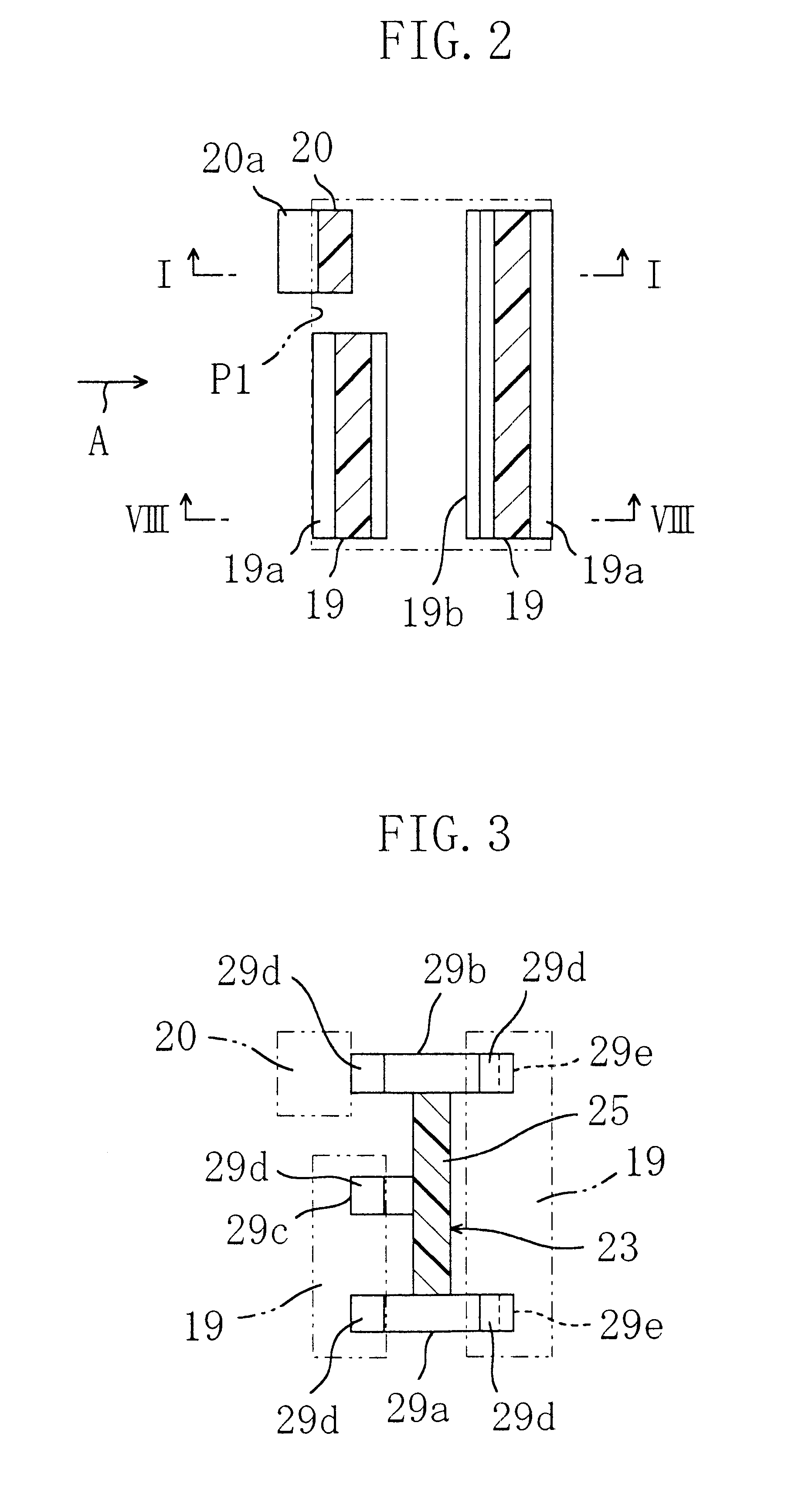
FIGS. 13 to 18 show an assist grip G to which mounts 3A and 3B according to Embodiment 2 are applied. This embodiment is different from Embodiment 1 in that the provisional retention pawl 20a of the provisional retention piece 20 is extended lengthwise of the engaging piece 19, that the locking member 23 includes a stop 29f, extended from the extension 29b, for blocking movement of the provisional retention piece 20 opposite to a direction of engagement by abutment of the stop 29f on the back face of the provisional retention piece 20, and that one of the raised portions 9f of the mount body 9 is formed with a slit 9j for preventing the stop 29f from interfering with the raised portion 9f in inserting the locking member 23 into the through hole 17. The other structures of this embodiment are the same as in Embodiment 1.

Accordingly, this embodiment provides the same effects and operations as in Embodiment 1.

Each of the foregoing embodiments describes, as an example, the...


PUM


Abstract

A pair of mounts 3A and 3B for an assist grip G each include a pair of engaging pieces 19 which are pushed apart from each other by press-insertion of a locking member 23 between them and thereby engaged on the edge of a panel opening p1 of an inner panel P. On at least one of both sides of the mount 3A (3B) where the pair of engaging pieces 19 are located, a provisional retention piece 20 is provided which is independent of and separated from the engaging piece 19. In mounting the assist grip G to the inner panel P through the panel opening p1, the provisional retention piece is inserted together with the engaging pieces 19 into the panel opening p1 and thereby engaged on the edge of the panel opening p1 to provisionally retain the mount 3A (3B) onto the inner panel P. This provides ease and reliable provisional retention and full retention of the mount with a small force.

Description

This invention relates to a mount for an assist grip equipped in a passenger room of a vehicle.Assist grips for vehicles are broadly classified as retractable type and fixed type. The former retractable assist grip includes a grip body with legs at both lengthwise ends and a pair of mounts onto which the corresponding legs of the grip body are mounted for swing motion. Thus, with the mounts attached to a car body panel through respective panel openings, the retractable assist grip can be swung between its retracted position and use position.As a retractable assist grip of such kind, there is known an assist grip as for example disclosed in U.S. Pat. No. 4,981,322 which aims at easily and readily mounting the assist grip in the panel openings. In this assist grip, a mount body of each mount is formed with a through hole and a pair of engaging pieces each having a pawl at the distal end thereof are extended from the periphery of the through hole on the back of the mount body.In mounti...

Claims


Application Information

Patent Timeline
Patent Type & Authority Patents(United States)
IPC IPC(8): B60N3/02
CPCB60N3/023B60N3/026
Inventor NODA, HOZUMI
Owner DAIKYONISHIKAWA CORP
Why Eureka
Try Eureka