Lens-fitted photo film unit capable of changing over aperture stop

a technology of lens-fitting and photo film, which is applied in the direction of exposure control, printing, instruments, etc., can solve the problems of blurred and low contrast of printed images, requiring much time to expose to photographic paper in printing operation, and increasing the cost of printing

Inactive Publication Date: 2002-08-06
FUJIFILM CORP +1
View PDF6 Cites 2 Cited by
  • Summary
  • Abstract
  • Description
  • Claims
  • Application Information

AI Technical Summary

Problems solved by technology

In under-exposed condition, a printed image is blurred and low-contrasted, and the graininess becomes worse.
In over-exposed condition, on the other hand, it requires much time to expose to a photographic paper in the printing operation.
Since a complex or an expensive mechanism is not be applicable to a cheap camera like a film unit, exposure changeover mechanism by means of moving a stop plate with a stop-down opening is applied to the film unit.
Therefore, when fluxes are separated on a shutter blade due to inserting a stop-down opening, exposure unevenness is likely to be conspicuous.
However, it is difficult to move the position of the shutter blade, because the shutter blade is required to keep a film chamber dark and it is a member rendering by shutter release operation.
As illustrated in FIGS. 18A and 18B, in changing over photographic lenses with different focal lengths, same problem described above occurs because the optimum positions of stop openings are different.
For the same reason described above, exposure unevenness is likely to occur.
It makes difficult to design the photographic lenses freely.
However, because of the spherical aberration, the object distance is different when the exposure opening is inserted on the optical axis, to cause the shift of focus.
In that case, it is hard to improve optical performance at any distance by inserting the stop-down opening.
Besides, a photographic lens used in the film unit is required to provide at a low cost, the chromatic aberration is corrected insufficiently.
In that case, it is hard to improve optical performance by inserting a stop-down opening.

Method used


Image

  • Lens-fitted photo film unit capable of changing over aperture stop
  • Lens-fitted photo film unit capable of changing over aperture stop
  • Lens-fitted photo film unit capable of changing over aperture stop

Examples


Embodiment Construction

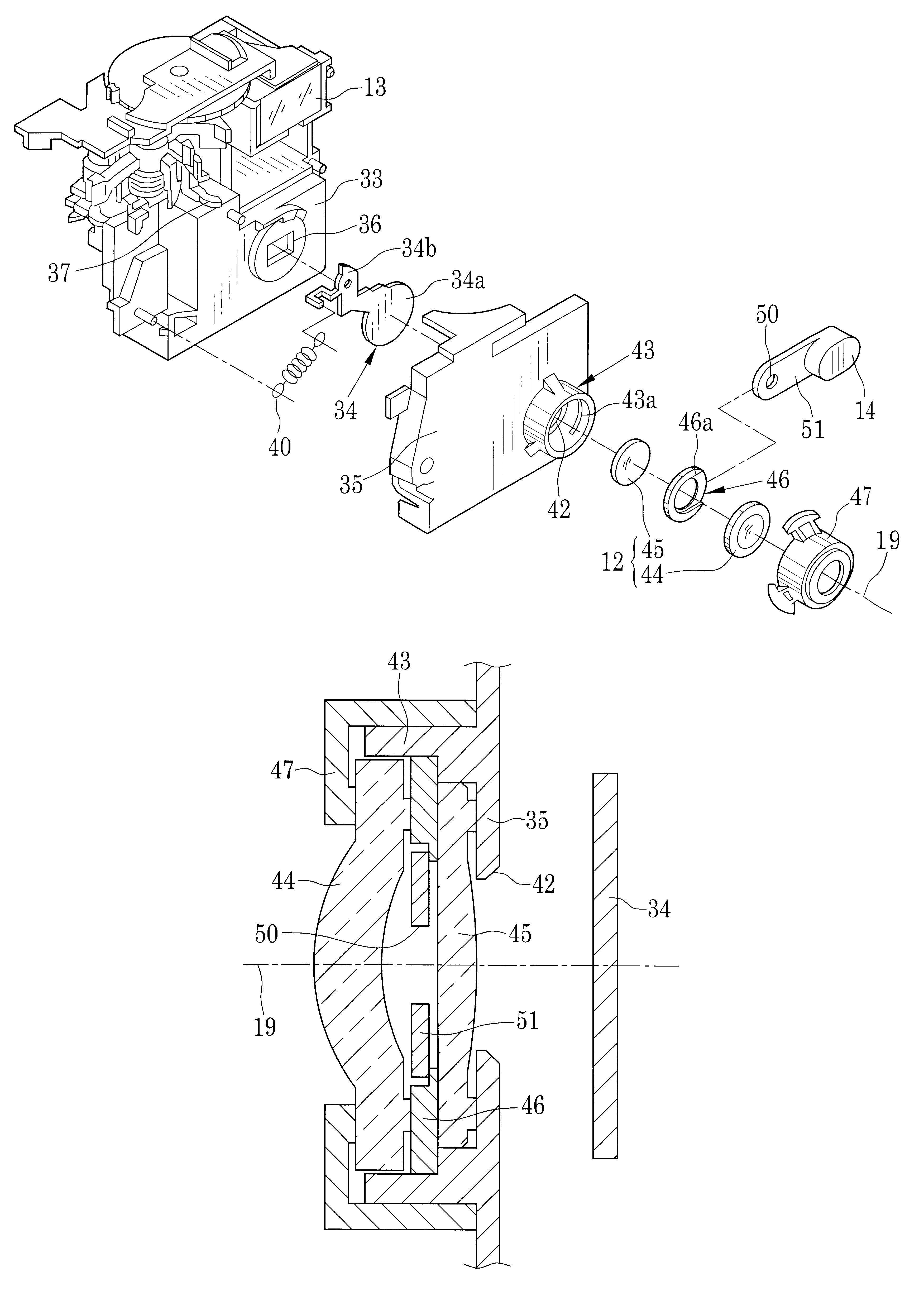
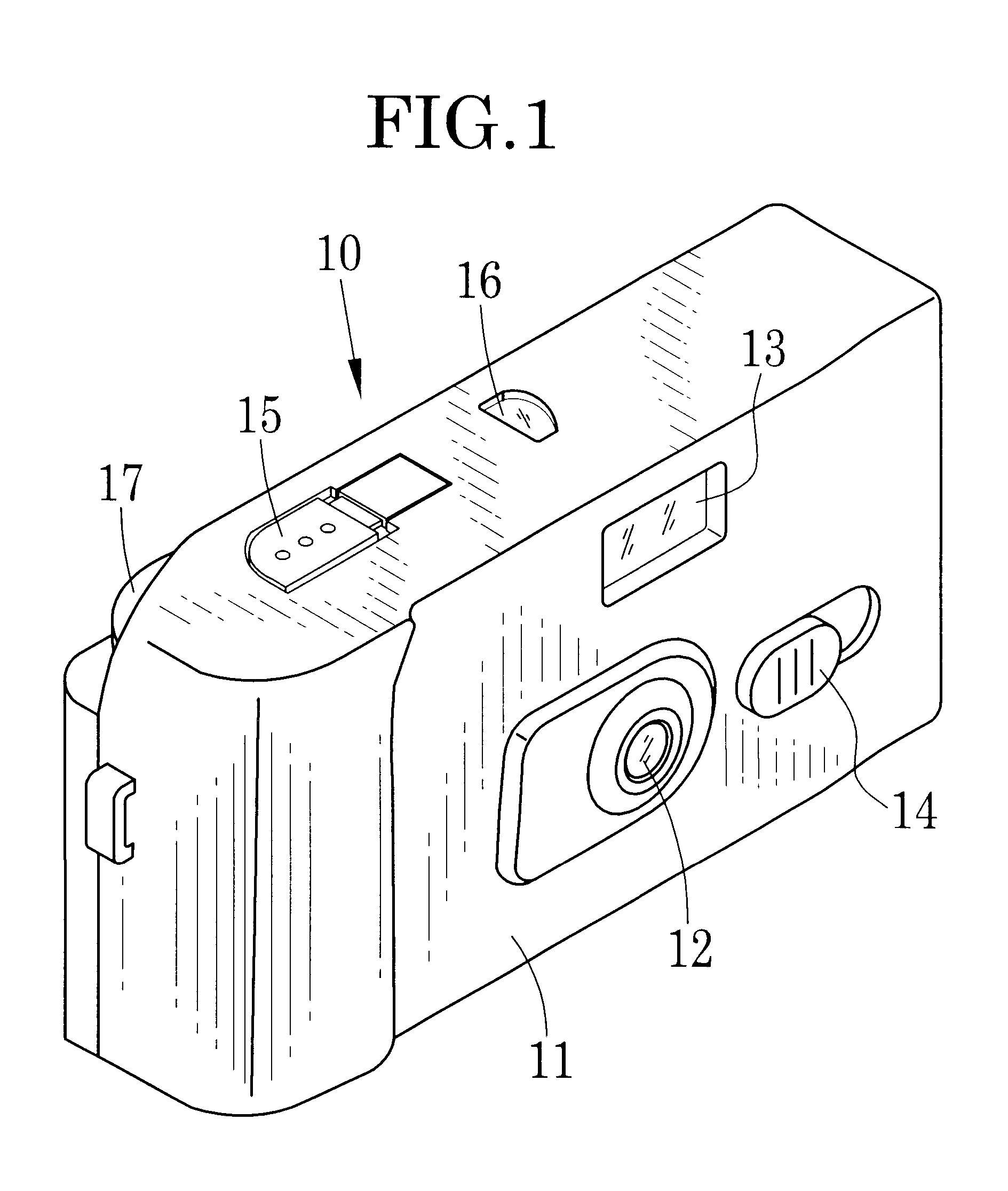
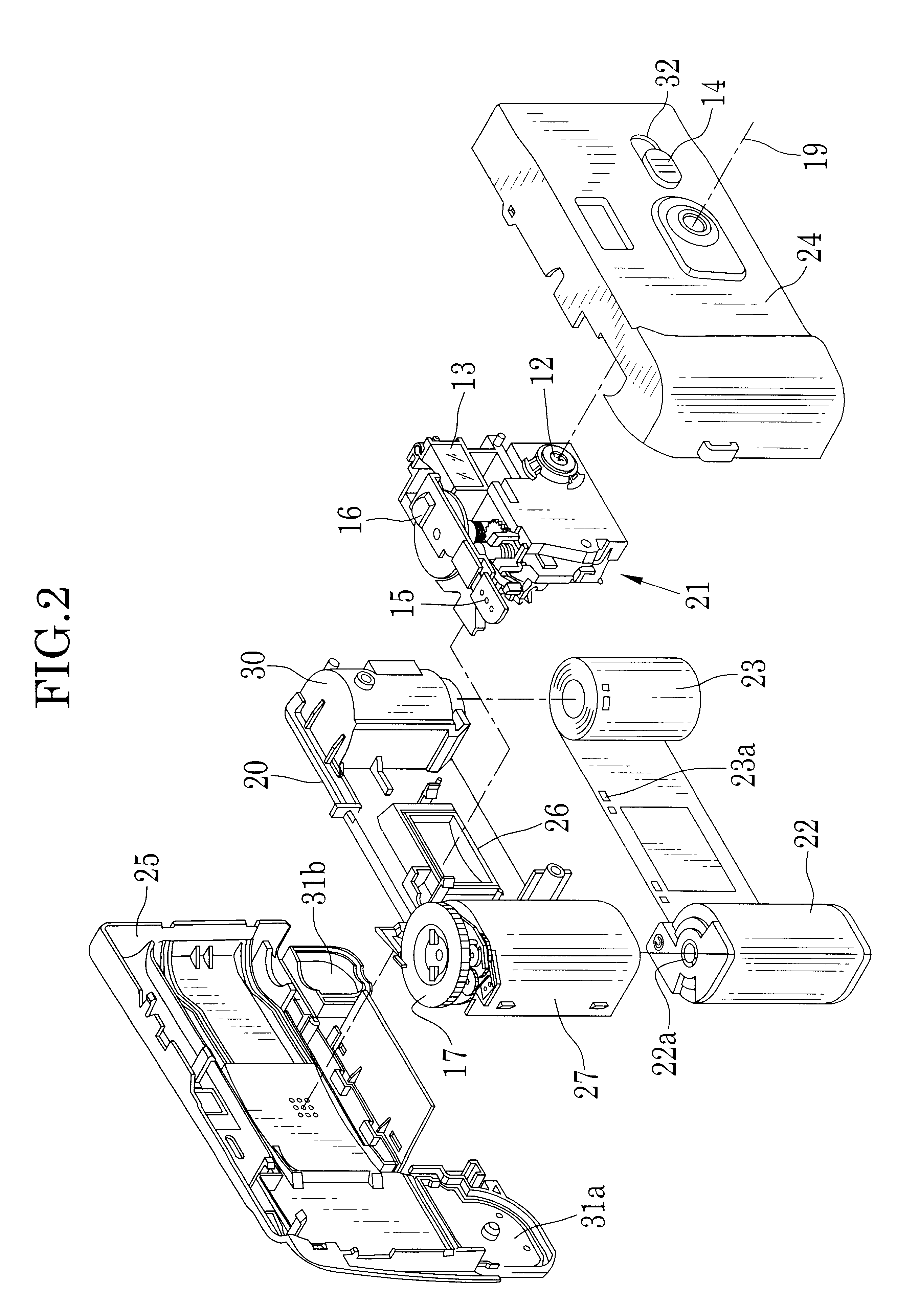
FIG. 1 is a perspective view illustrating a film unit. The film unit is comprised of a housing 10 having kinds of photographic mechanisms and a wrapping label 11 rolled around the housing 10. A photographic lens 12, a viewfinder 13, a changeover knob 14 are provided on a front wall of the housing 10. A shutter button 15 and a frame counter 16 are provided on the top wall, and a part of a winding wheel 17 emerges in the back wall of the housing 10.

The housing 10, as illustrated in FIG. 2, includes a basic portion 20, an exposure unit 21, a photo film cassette 22, a photo film 23, a front cover 24, and a rear cover 25. The basic portion 20 includes an exposure aperture 26 which determines the frame region on the photo film 23, and a cassette chamber 27 which contains the photo film cassette 22, and a film roll chamber 30 which contains a roll of the photo film 23.

The winding wheel 17 is rotatably attached to the top wall of the cassette chamber 27, and a shaft formed downwards therewi...


PUM


Abstract

A first lens element and a second lens element for comprising a photographic lens, and a stop opening are arranged on an optical axis in this order. A stop plate has a stop-down opening. The stop plate is movable between a first position where the stop-down opening is inserted on an optical axis between the first and the second lens elements for making an f-number of the photographic lens f1, and a second position where the stop-down opening is retracted from the optical axis for making the f-number f2. The photographic lens is constructed to satisfy the following conditions:wherein L(%) represents a proportion of brightness in a marginal portion of a frame to brightness in a central portion of the frame at the time when the stop-down opening is inserted, and E(EV) represents the difference between the maximum exposure amount and the minimum exposure amount in the marginal portion of the frame.

Description

1. Field of the InventionThe present invention relates to a lens-fitted photo film unit having a exposure control mechanism by stop changeover, more particularly, the present invention relates to a lens-fitted photo film unit preventing deterioration of image quality due to change of the stop position.2. Background ArtsA variety of lens-fitted photo film units, having a pre-loaded photo film and photographic mechanisms like a photographic lens and a shutter mechanism, are manufactured and sold. In order to reduce the manufacturing cost, the lens-fitted photo film unit, hereinafter called simply film unit, is comprised as simple as possible. For instance, a lens holder having a fixed stop opening and a struck-type shutter blade are applied to the film unit. The values of f-number and shutter speed are fixed, and the photographing condition is also fixed.Therefore, under a severe photographing condition, there is a case where an exposure amount is out of the latitude. In under-exposed...

Claims


Application Information

Patent Timeline
Patent Type & Authority Patents(United States)
IPC IPC(8): G03B9/02G03B5/02G03B7/20G03B7/085G03B9/04G03B9/10G03B17/12
CPCG03B5/02G03B7/20G03B9/02G03B9/04G03B9/10G03B17/12G03B2219/045G03B7/085
Inventor KOIKE, KAZUMIMASUDA, TAKESHIMIKAMI, YUJI
Owner FUJIFILM CORP
Why Eureka
Try Eureka