Magnetically shielded electrodeless light source

a technology of electromagnetic shielding and light source, which is applied in the direction of electric variable regulation, process and machine control, instruments, etc., can solve the problems of difficult or expensive replacement of lamps, inability to easily access lamps, and major life-limiting components of electric fluorescent lamps

Inactive Publication Date: 2002-08-13
L 3 COMM CORP
View PDF4 Cites 76 Cited by
  • Summary
  • Abstract
  • Description
  • Claims
  • Application Information

AI Technical Summary

Problems solved by technology

The electrodes, however, are major life-limiting components of the fluorescent lamp.
Thus, electrodeless lamps are particularly useful in applications in which access to the lamps is restricted such that replacement of the lamps becomes difficult or expensive.
Backlit video display devices are one type of application in which the access to the lamp is not readily available.
However, such video displays often are located in environments in which the ambient lighting conditions vary considerably, interfering with vivid viewing of the displayed image.
Unfortunately, electrodeless lamps rarely are used in such displays due to the lack of suitable means for dimming such lamps.
However, when used as a backlight source, the inventor has noted that video artifacts (e.g., dark horizontal stripes or bars) may appear on the display when the lamp is energized.
These artifacts, which may detract from or otherwise impair viewing of an image, are particularly noticeable when dimming circuitry is incorporated into the display system.
When the lamp is energized, AC lamp current flows therethrough and causes generation of a lamp magnetic field that may cause effects, such as visual artifacts, that may impair viewing of the image on the display unit.

Method used


Image

  • Magnetically shielded electrodeless light source
  • Magnetically shielded electrodeless light source
  • Magnetically shielded electrodeless light source

Examples


Embodiment Construction

One or more specific embodiments of the present invention will be described below. In an effort to provide a concise description of these embodiments, not all features of an actual implementation are described in the specification. It should be appreciated that in the development of any such actual implementation, as in any engineering or design project, numerous implementation-specific decisions must be made to achieve the developers' specific goals, such as compliance with system-related and business-related constraints, which may vary from one implementation to another. Moreover, it should be appreciated that such a development effort might be complex and time consuming, but would nevertheless be a routine undertaking of design, fabrication, and manufacture for those of ordinary skill having the benefit of this disclosure.

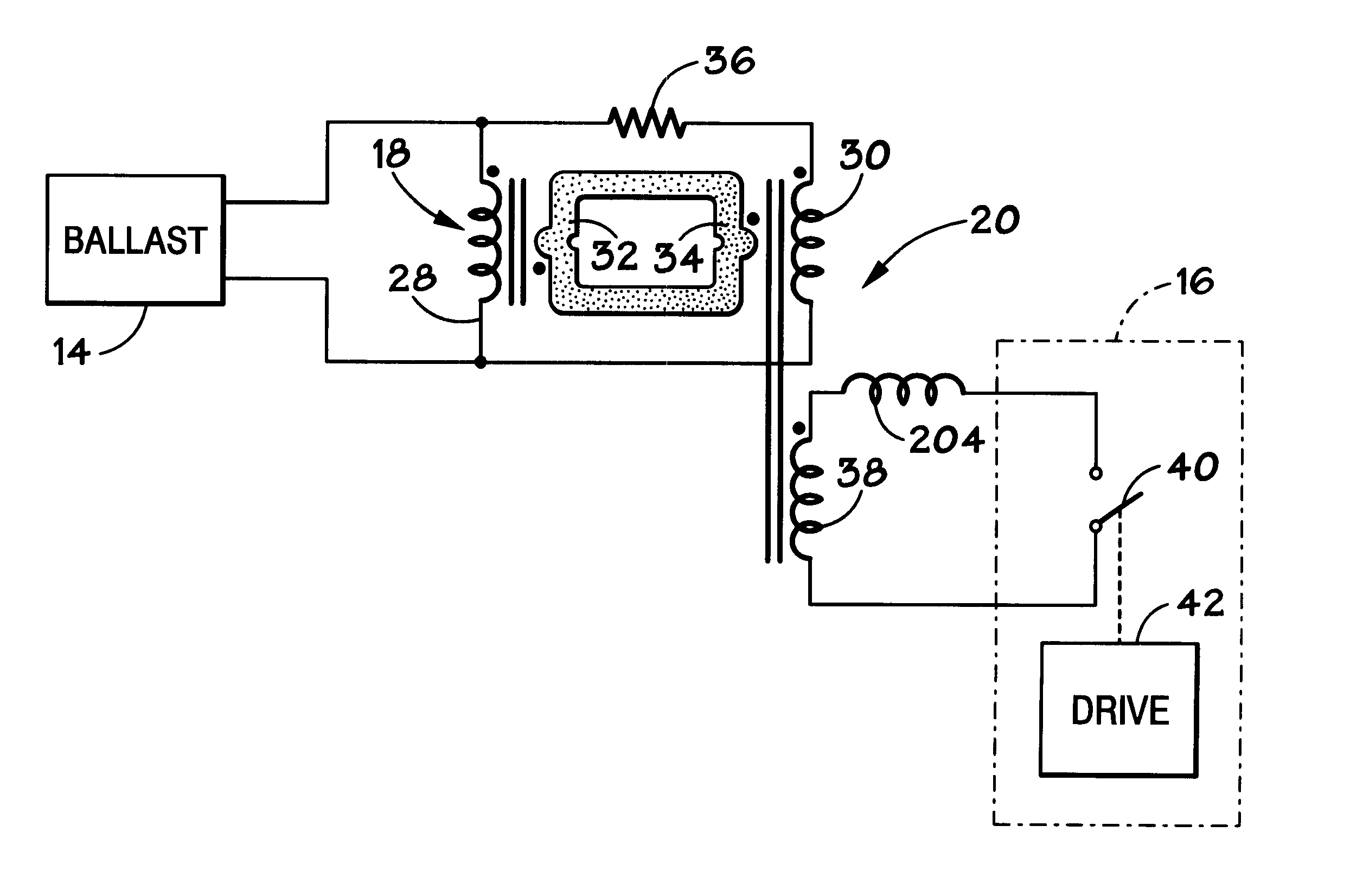
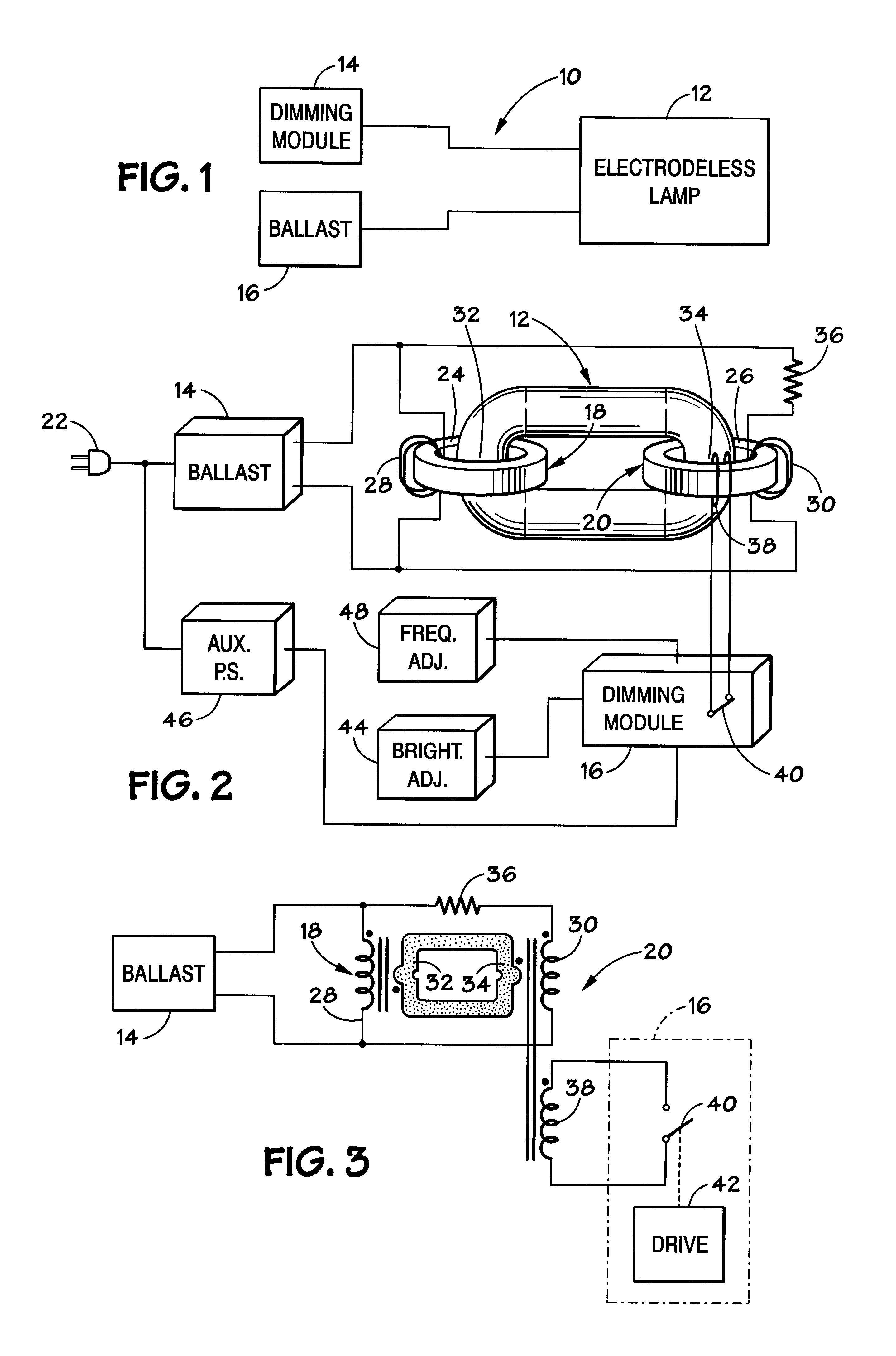
Turning now to FIG. 1, a block diagram of a dimmable light source 10 is illustrated. The dimmable light source 10 includes an electrodeless lamp 12, an AC power...


PUM


Abstract

A dimmable electrodeless light source includes an electrodeless lamp, an electronic ballast and a dimming module. The light source further includes coupling transformers coupled to the electrodeless lamp for inductively coupling power to the lamp to generate light. An auxiliary winding electromagnetically coupled to the primary winding of at least one of the coupling transformers is driven by switching circuitry in the dimming module. The switching circuitry is pulse width modulated to control the average brightness of the light generated by the electrodeless lamp. An exemplary application for the dimmable electrodeless light source is as a backlight for a video display device, such as a liquid crystal display unit. The dimmable electrodeless light source further includes a magnetic shield device that is operably positioned with respect to the electrodeless lamp. The magnetic shield device produces a magnetic field that substantially opposes, and cancels, the magnetic field that is produced by the electrodeless lamp when energized. In an alternative embodiment, the magnetic shield device produces a magnetic field which, when combined with the lamp magnetic field, results in a total magnetic field that is substantially constant regardless of the energization level of the lamp (e.g., totally energized or dimmed). The magnetic shield thus reduces visual artifacts that might otherwise appear on a video display unit due to a variation of the magnetic field produced by the lamp.

Description

1. Field of The InventionThe present invention relates generally to electrodeless light sources and, more particularly, to a method and apparatus for shielding electromagnetic interference generated by an electrodeless fluorescent light source for a backlit display.2. Background of the Related ArtThis section is intended to introduce the reader to various aspects of art which may be related to various aspects of the present invention which are described and / or claimed below. This discussion is believed to be helpful in providing the reader with background information to facilitate a better understanding of the various aspects of the present invention. Accordingly, it should be understood that these statements are to be read in this light, and not as admissions of prior art.Conventional fluorescent lamps are driven with an electronic ballast which powers the lamps via electrodes disposed at each end of the lamp. The electrodes, however, are major life-limiting components of the fluor...

Claims


Application Information

Patent Timeline
Patent Type & Authority Patents(United States)
IPC IPC(8): H05B41/24
CPCH05B41/24Y10S315/04
Inventor BUONAVITA, CARL E.
Owner L 3 COMM CORP
Why Eureka
Try Eureka