Method and apparatus for automatically adjusting the characteristics of a dielectric filter

a technology of automatic adjustment and filter, which is applied in the direction of transmission, waveguide type devices, line-transmission details, etc., can solve the problems of inability to carry out a constant stabilization manufacturing process, inability to accurately adjust the characteristics of objects, and inability to continuously stabilize the manufacturing process

Inactive Publication Date: 2002-08-20
MURATA MFG CO LTD
View PDF9 Cites 24 Cited by
  • Summary
  • Abstract
  • Description
  • Claims
  • Application Information

AI Technical Summary

Problems solved by technology

However, since there are in fact some irregularities in these characteristics, such irregularities should be taken into account in the actual design process.
However, because perturbations caused by the cutting or adding or the insertion or removal of a dielectric material or an electrically conductive material in certain adjustment positions for adjusting the above-mentioned characteristics, a characteristic change of an object being adjusted is not necessarily linear.
This however, results in a problem, namely that productivity is low and it is impossible to carry out a constantly stabilized manufacturing process.
However, with a plurality of resonance modes, it is impossible to adjust the resonance frequency of one resonator (which may be referred to as an adjustment object) completely independently of other resonators.
For instance, if certain portions of the dielectric column are cut off, the resonance frequencies of several resonance modes will be undesirably changed at the same time.
For this reason, in a case when it is required to adjust the characteristics of a dielectric filter employing several triple mode resonators, it is no longer substantially possible to use a method in which a human operator is allowed to perform the adjustment while at the same time adjusting the characteristics of the filter with a network analyzer.

Method used


Image

  • Method and apparatus for automatically adjusting the characteristics of a dielectric filter
  • Method and apparatus for automatically adjusting the characteristics of a dielectric filter
  • Method and apparatus for automatically adjusting the characteristics of a dielectric filter

Examples


Embodiment Construction

A method and an apparatus for automatically adjusting the characteristics of a dielectric filter, in relation to an embodiment of the present invention, will be described in the following with reference to FIGS. 1 to 6.

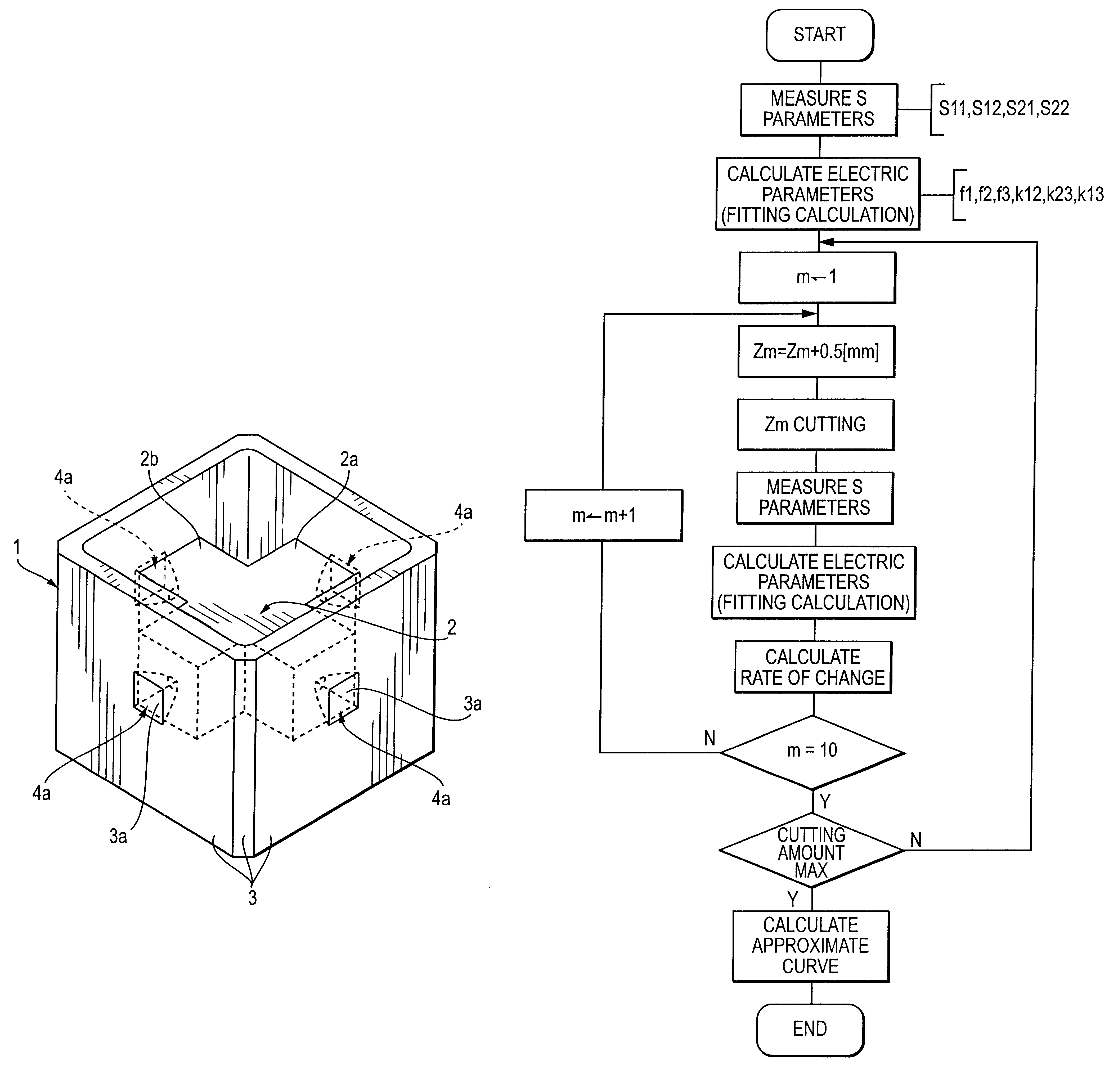
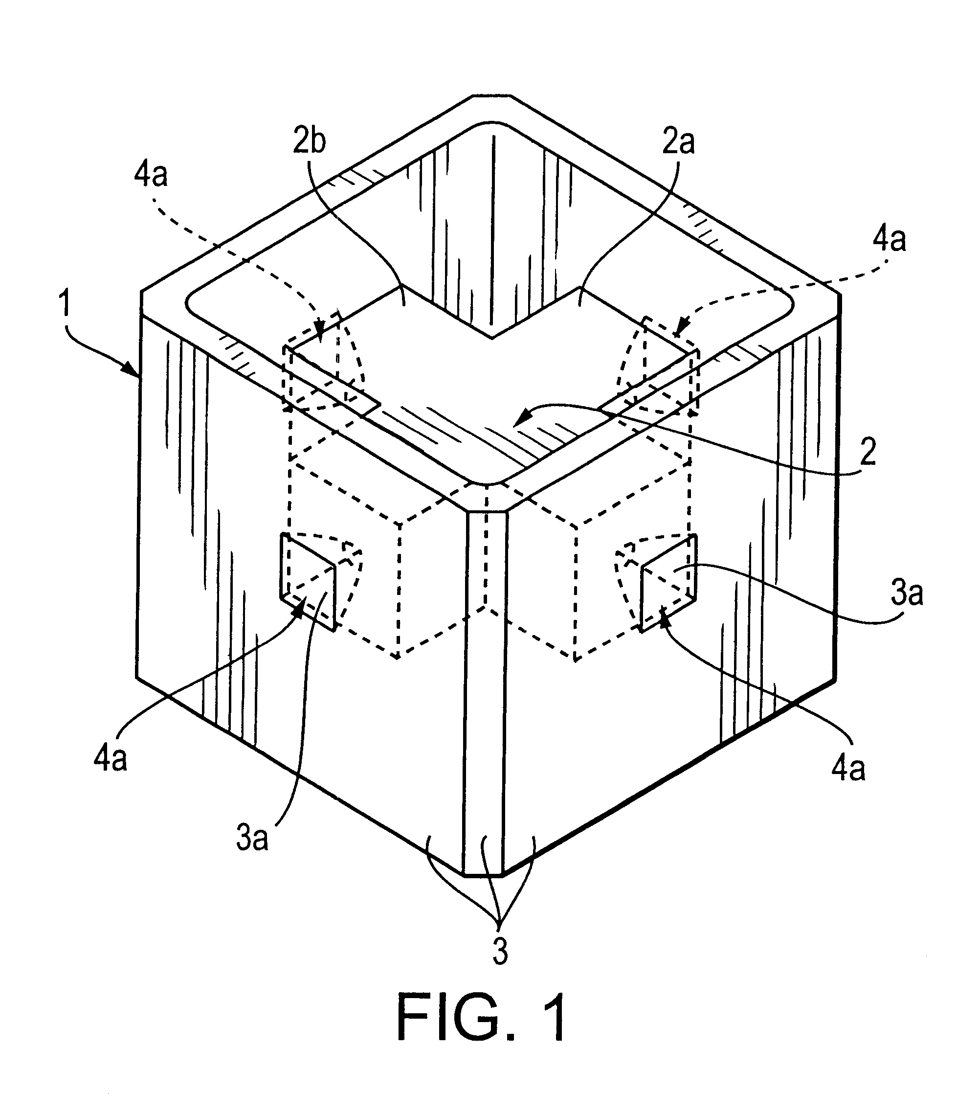
FIG. 1 is a perspective view schematically indicating some important portions of a dielectric filter which is used as an example of a method for adjusting its characteristics. In FIG. 1, reference numeral 1 is used to represent a dielectric cavity within which there is integrally formed a composite dielectric column 2 having two dielectric columns 2a and 2b arranged in a mutually orthogonal relationship with each other. Corresponding to each end face of each of the two dielectric columns 2a and 2b and near the center of each wall of the cavity 1, a respective recess portion 4a is formed, extending from the outer surface of the corresponding wall inwardly into a deep position in the corresponding one of the dielectric columns 2a and 2b. An electrically conductive mater...


PUM


Abstract

A method and an apparatus for exactly and automatically adjusting the characteristics of a dielectric filter in a short time period. The characteristic parameters of a dielectric filter are measured, electric parameters of a designed equivalent circuit of the filter are calculated with the use of characteristic parameters, characteristic adjusting portions of the dielectric filter are adjusted, while at the same time, adjustment functions indicating the variation amounts of electric parameters with respect to adjusting amounts are calculated with the use of the electric parameters and the adjusting amounts which have been changed by the above adjustment. Then, in accordance with simultaneous equations involving adjustment functions, an adjusting amount is calculated with the use of a difference between a present electric parameter and a desired electric parameter, thereby effecting an adjustment which is for example 50%. By repeatedly conducting the above treatments, the characteristic parameters of the filter will be allowed to successively get closer to the desired values.

Description

1. Field of the InventionThe present invention relates to a method of and an apparatus for automatically adjusting the characteristics of a dielectric filter.2. Description of the Related ArtTypical dielectric filters are composed of electromagnetically coupled dielectric resonators. Each resonator is formed by a dielectric with an electrode film on it.In order to obtain a dielectric filter having desired characteristics, a method has been used in which some electrode portions or some dielectric portions are cut so as to be removed, and / or alternatively some adjustment screws are driven so as to insert or remove some dielectric members or some metal members, thereby effecting a desired characteristic adjustment.If physical properties of the materials forming a dielectric filter are made constant and if sizes of various portions of the dielectric filter are maintained with extremely high precision, it will be allowed to obtain substantially constant characteristics all the time. Howe...

Claims


Application Information

Patent Timeline
Patent Type & Authority Patents(United States)
IPC IPC(8): H01P11/00H01P7/10H01P1/16H01P1/205H01P1/20H01P1/208
CPCH01P7/10H01P11/008H01P1/205H01P1/16
Inventor ANDOH, MASAMICHIKUBOTA, KAZUHIKO
Owner MURATA MFG CO LTD
Why Eureka
Try Eureka