
Dynamic range reducing volume control

a volume control and dynamic range technology, applied in the field of audio compression, can solve the problems of reducing the listening enjoyment of one's listener, reducing the listening enjoyment of the listener, and turning the compressor on and off, so as to increase the listening level of quieter passages, reduce the compression ratio, and increase the compression ratio

Active Publication Date: 2005-08-11
CIRRUS LOGIC INC
View PDF7 Cites 52 Cited by
  • Summary
  • Abstract
  • Description
  • Claims
  • Application Information

AI Technical Summary

Benefits of technology

[0004] The present invention provides an audio amplifier having an automatically-adjusting compressor. Compression is linked to the volume control in an inverse relationship whereby, when the volume is reduced, the compression ratio is increased to boost the listening level of quieter passages in the source material. Conversely, when the volume is increased, the compression ratio is decreased. The compression control may be physically connected to the volume control, such as in a dua

Problems solved by technology

However, if the volume is reduced, quiet passages may become inaudible and one's listening enjoyment is reduced.
However, the fixed compression ratio may be adequate for only a limited number of listening situations.
Moreover, turning the compressor on and off is an inconvenience to the listener.
As is known, compression tends to reduce audio quality and should be used sparingly, if at all.
And, an inexperienced listener (or one who doesn't like the inconvenience of dual adjustments) may simply leave the compressor off or leave it on with the compression set to some arbitrary ratio rarely, if ever, changing it.

Method used


Image

  • Dynamic range reducing volume control
  • Dynamic range reducing volume control
  • Dynamic range reducing volume control

Examples


Embodiment Construction

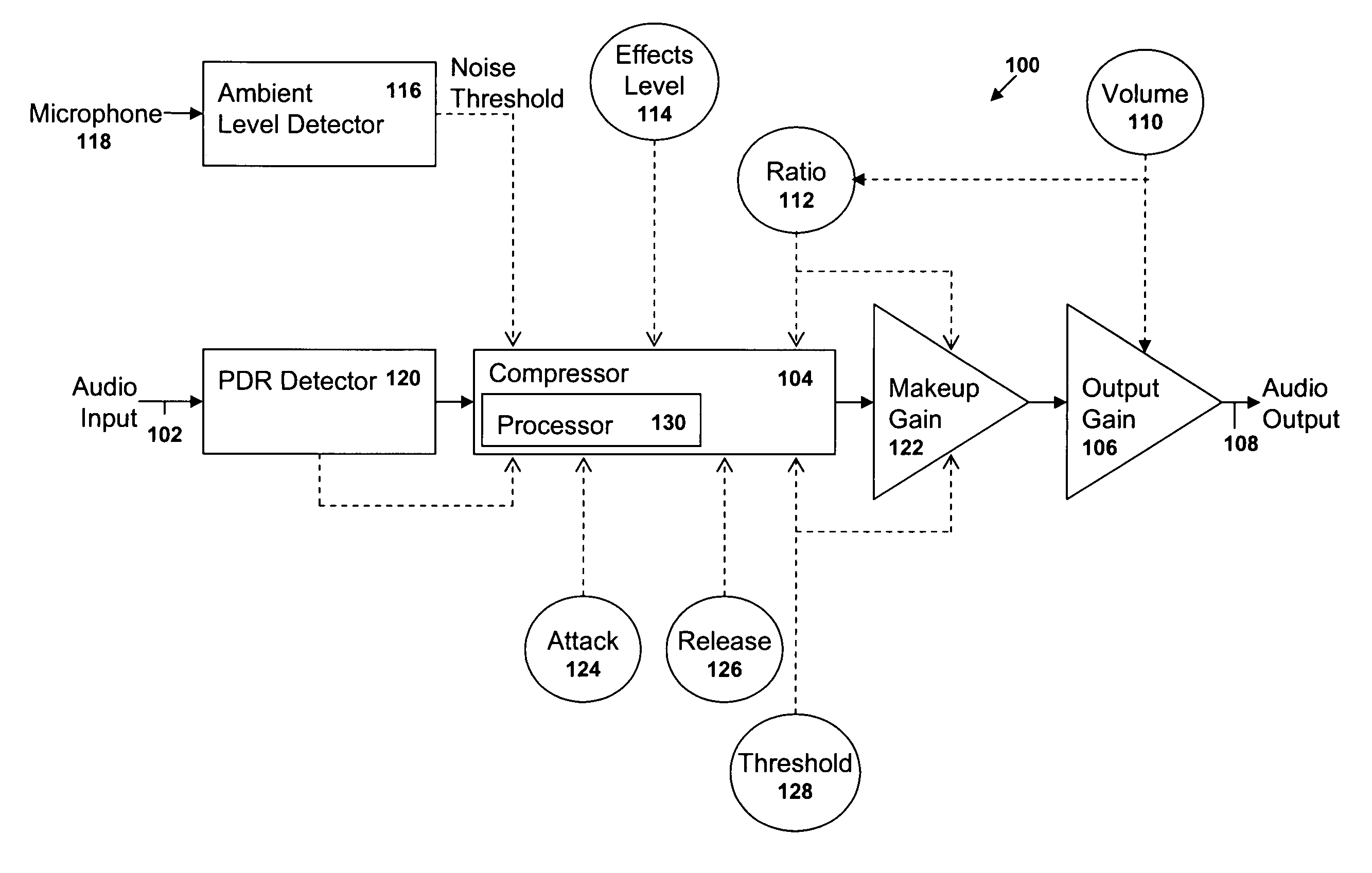
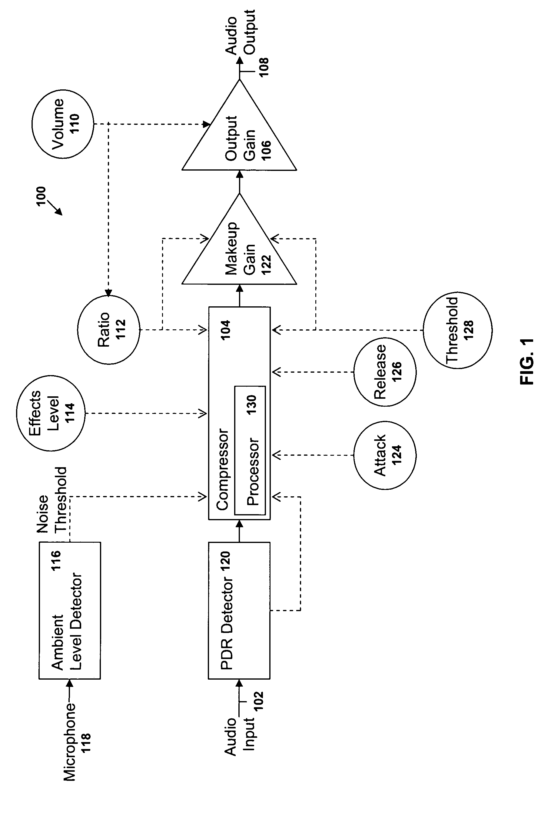
[0010]FIG. 1 is a block diagram of an audio amplifier 100 of the present invention with dynamically adjustable compression. The amplifier 100 includes an audio input 102, a compressor 104, an audio gain stage 106 and an audio output 108. The amplifier 100 further includes a volume control 110 and a compression ratio control 112. The compression control 112 establishes a compression ratio which is applied to audio program material processed by the compressor 104. Compressed audio is output to the audio gain stage 106. The volume control 110 provides an audio level signal in response to adjust the volume V of the audio output from the audio gain stage 106.

[0011] The volume control 110 is also coupled to the compression control 112. In one embodiment, the volume control 110 and a compression control 112 are each part of a dual-potentiometer. In another embodiment, the compression control 112 is included in a digital signal processor (DSP) having an input coupled to the volume control ...


PUM


Abstract

An audio amplifier is provided having a compressor with an automatically-adjustable compressor. Compression is linked to the volume control in an inverse relationship whereby, when the volume is reduced, the compression ratio is increased to boost the listening level of quieter passages in the source material. Conversely, when the volume is increased, the compression ratio is decreased. The compression control may be physically connected to the volume control, such as in a dual-potentiometer, or may be coupled electronically, such as with a digital signal processor. An effects level control may be included to allow a listener to increase or decrease the effect of the compression by applying a multiplier to the compression ratio. An ambient noise detector may also be included such that compression is increased as ambient noise increases or exceeds a predetermined level.

Description

TECHNICAL FIELD [0001] The present invention relates generally to audio compression and, in particular, to dynamically adjusting compression in an inverse manner relative to volume. BACKGROUND ART [0002] In many applications of audio equipment, such as televisions, stereo amplifiers CD players and the like, music and other recorded (or live) material generally includes both loud passages and quiet passages. If the audio volume is high enough (such as in a noisy environment), both quiet and loud passages a sufficiently audible. However, if the volume is reduced, quiet passages may become inaudible and one's listening enjoyment is reduced. [0003] A compressor may be inserted into the audio path. If the compressor has a fixed compression ratio, it may be turned on and off as desired by the listener. However, the fixed compression ratio may be adequate for only a limited number of listening situations. Moreover, turning the compressor on and off is an inconvenience to the listener. If t...

Claims


Application Information

Patent Timeline
IPC IPC(8): H03G7/00
CPCH03G7/002
Inventor ANDERSON, CHARLES
Owner CIRRUS LOGIC INC
Learn More