Systems and methods for automatically adjusting channel timing

a technology of automatic adjustment and channel timing, applied in the field of audio amplification systems, can solve the problems of low performance applications, complex and costly applications to implement, and unwidely accepted solutions, and achieve the effect of improving dead time and shooting conditions

Active Publication Date: 2006-04-04
INTERSIL INC
View PDF5 Cites 52 Cited by
  • Summary
  • Abstract
  • Description
  • Claims
  • Application Information

AI Technical Summary

Benefits of technology

[0012]One or more of the problems outlined above may be solved by the various embodiments of the invention. Broadly speaking, the invention comprises systems a

Problems solved by technology

More particularly, these attempts utilized analog modulation schemes that resulted in low performance applications.
These applications were complex and costly to implement.
Consequently, these solutions were not widely accepted.
Prior art analog implementations of Class D technology have therefore been unable to displace legacy Class AB amplifiers in mainstream amplifier applications.
These digital PWM schemes, however, did little to offset the major barriers to integration of PWM modulators into the total amplifier solution.
Class D technology has therefore continued to be unable to displace legacy Class AB amplifiers in mainstream applications.
One of the problems with prior art systems and methods is that they do not provide a mechanism for automatically adjusting the timing of si

Method used


Image

  • Systems and methods for automatically adjusting channel timing
  • Systems and methods for automatically adjusting channel timing
  • Systems and methods for automatically adjusting channel timing

Examples


Embodiment Construction

[0024]One or more embodiments of the invention are described below. It should be noted that these and any other embodiments described below are exemplary and are intended to be illustrative of the invention rather than limiting.

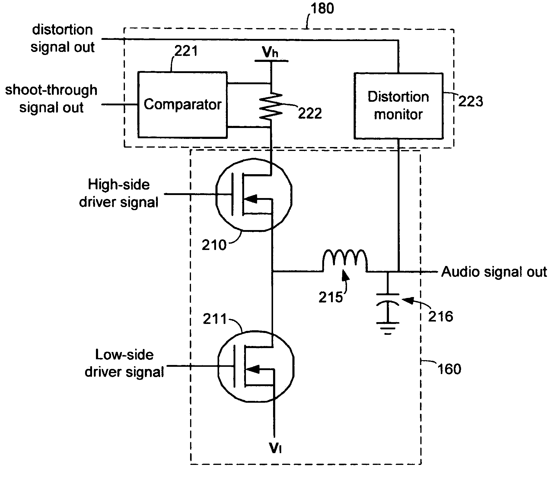
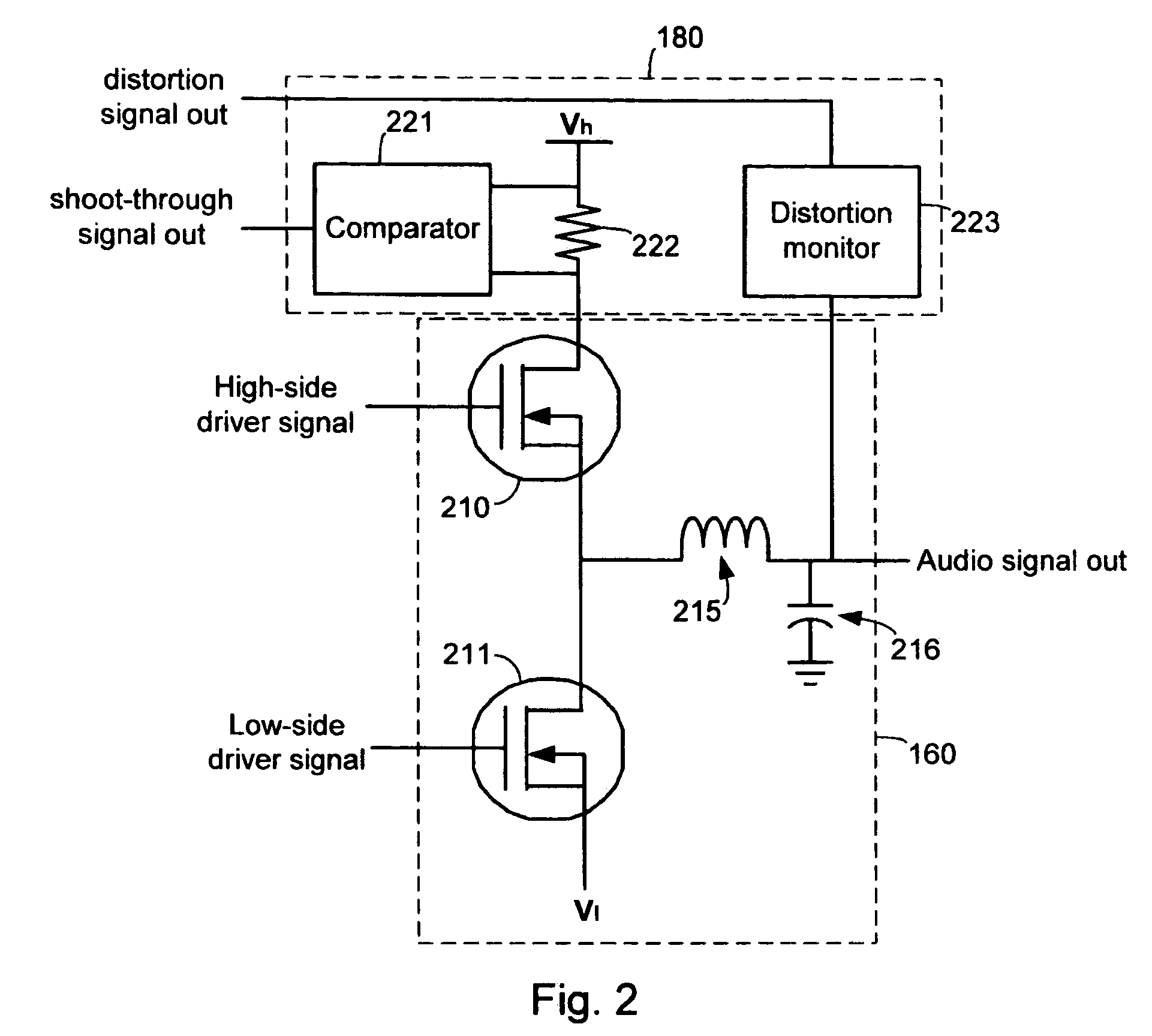
[0025]As described herein, various embodiments of the invention comprise systems and methods for automatically adjusting the alignment of high-side and low-side pulse width modulated signals to improve dead time and shoot-through conditions.

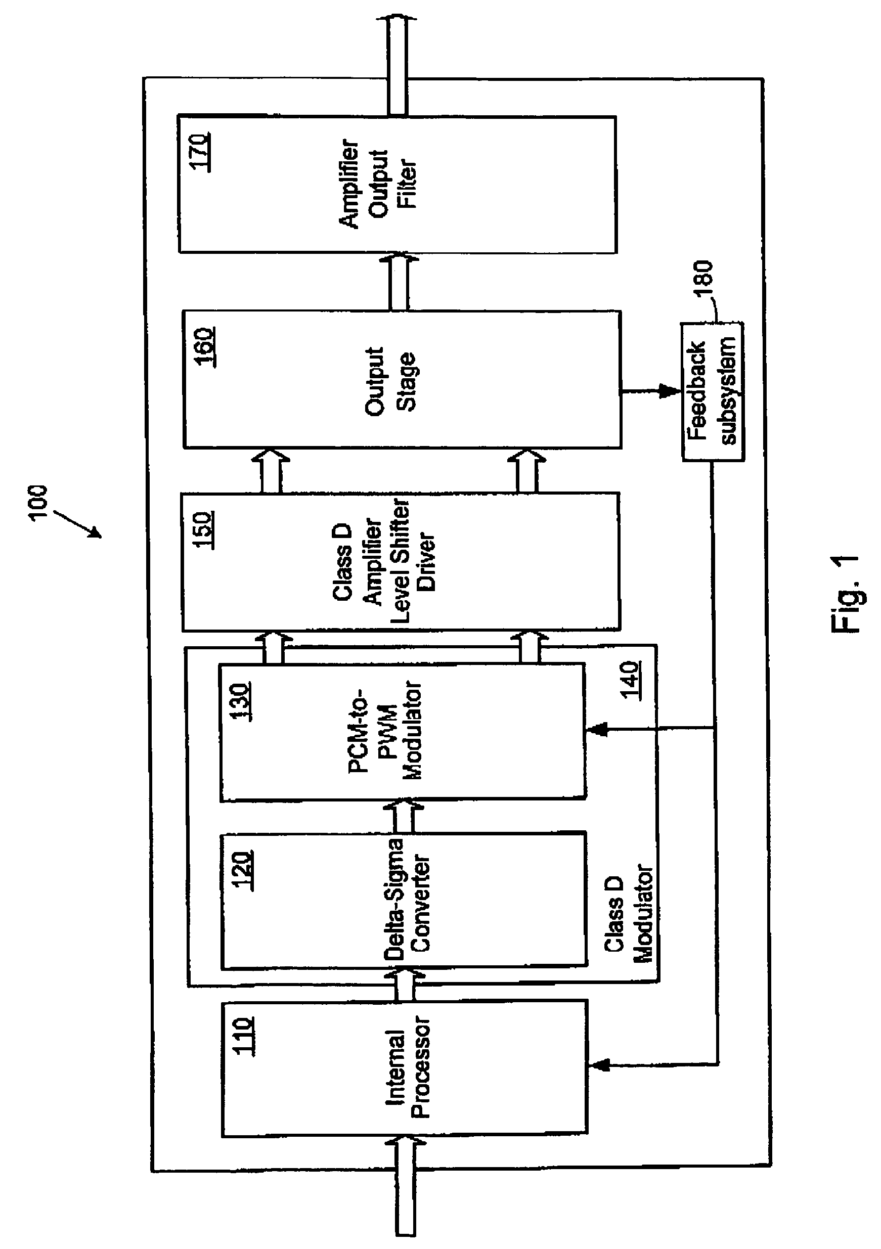
[0026]One embodiment comprises a method for adjusting the relative timing of high-side and low-side signals in a digital PWM amplifier. Because the FETs in the output stage of the PWM amplifier do not switch perfectly (i.e., they do not switch instantaneously between being completely turned on and completely turned off), there is a period of time during which the FETs transition from a state in which a first one is turned on and a second one is turned off, to a state in which the first one is turned off and the second one ...


PUM


Abstract

Systems and methods for automatically adjusting the alignment of high-side and low-side pulse width modulated signals to improve dead time and shoot-through conditions. In one embodiment, a system includes a digital amplifier controller, an amplifier output stage coupled to the controller and configured to receive audio signals from the controller, and one or more sensors coupled to the output stage. The sensors are configured to detect and/or measure various parameters, such as shoot-through current and distortion, which are associated with the operation of the output stage. The sensors provide feedback to an internal processor or modulator of the controller, which then adjusts the timing of the high-side and low-side signals to improve the operating conditions of the output stage by minimizing shoot-through current and/or distortion.

Description

RELATED APPLICATIONS[0001]This application claims priority to U.S. Provisional Patent Application No. 60 / 456,421, entitled “Output Device Switch Timing Correction,” by Taylor, et al., filed Mar. 21, 2003; U.S. Provisional Patent Application No. 60 / 456,414, entitled “Adaptive Anti-Clipping Protection,” by Taylor, et al., filed Mar. 21, 2003; U.S. Provisional Patent Application No. 60 / 456,430, entitled “Frequency Response Correction,” by Taylor, et al., filed Mar. 21, 2003; U.S. Provisional Patent Application No. 60 / 456,429, entitled “High-Efficiency, High-Performance Sample Rate Converter,” by Andersen, et al., filed Mar. 21, 2003; U.S. Provisional Patent Application No. 60 / 456,422, entitled “Output Filter, Phase / Timing Correction,” by Taylor, et al., filed Mar. 21, 2003; U.S. Provisional Patent Application No. 60 / 456,428, entitled “Output Filter Speaker / Load Compensation,” by Taylor, et al., filed Mar. 21, 2003; U.S. Provisional Patent Application No. 60 / 456,420, entitled “Output St...

Claims


Application Information

Patent Timeline
IPC IPC(8): H03F3/38
CPCH03F1/32H03F3/181H03F3/217H03F2200/331H03F2200/03
Inventor TAYLOR, WILSON E.ANDERSEN, JACK B.ROVNER, MICHAELKOST, MICHAEL A.
Owner INTERSIL INC
Why Eureka
Try Eureka