Method of designing a building for maximum compatability with modular forms

a technology of modular buildings and modular forms, applied in the direction of form/shuttering/falseworks, building parts, construction, etc., can solve the problems of undesirable similarity of modular buildings, limiting the ability of structural engineers and owners to create new structures, and limiting the ability of architects and engineers to alter the appearance, size and shape of buildings

Inactive Publication Date: 2002-08-27
DELEFEVRE PATRICK
View PDF14 Cites 29 Cited by
  • Summary
  • Abstract
  • Description
  • Claims
  • Application Information

AI Technical Summary

Problems solved by technology

There still remains the problem of going from the original structure as defined by an original set of construction documents, drawings and the like, to the construction of the final building structure.
In the past, modular buildings have been undesirably similar because of the modules utilized.
Thus, modular buildings tend to look the same and function the same, thereby severely limiting the ability of architects, structural engineers and owners to create new structures while at the same time taking advantage of modular techniques.
For modular buildings, these decisions are pre-made, which is why modular building techniques have limited the ability of the architect and the engineer to alter the appearance, size and shape of the building.
As will be appreciated, the shear enormity of numbers of items to be specified for a given building limits the use of modular components by architects and structural engineers, such that modular systems, when employed, were used at the expense of architectural and engineering creativity.
While modular systems have existed in the past, in general, they limit flexibility.
On the other hand, modular construction techniques tend to limit the architect in what the architect can design because the modular elements are preset.

Method used


Image

  • Method of designing a building for maximum compatability with modular forms
  • Method of designing a building for maximum compatability with modular forms
  • Method of designing a building for maximum compatability with modular forms

Examples


example i

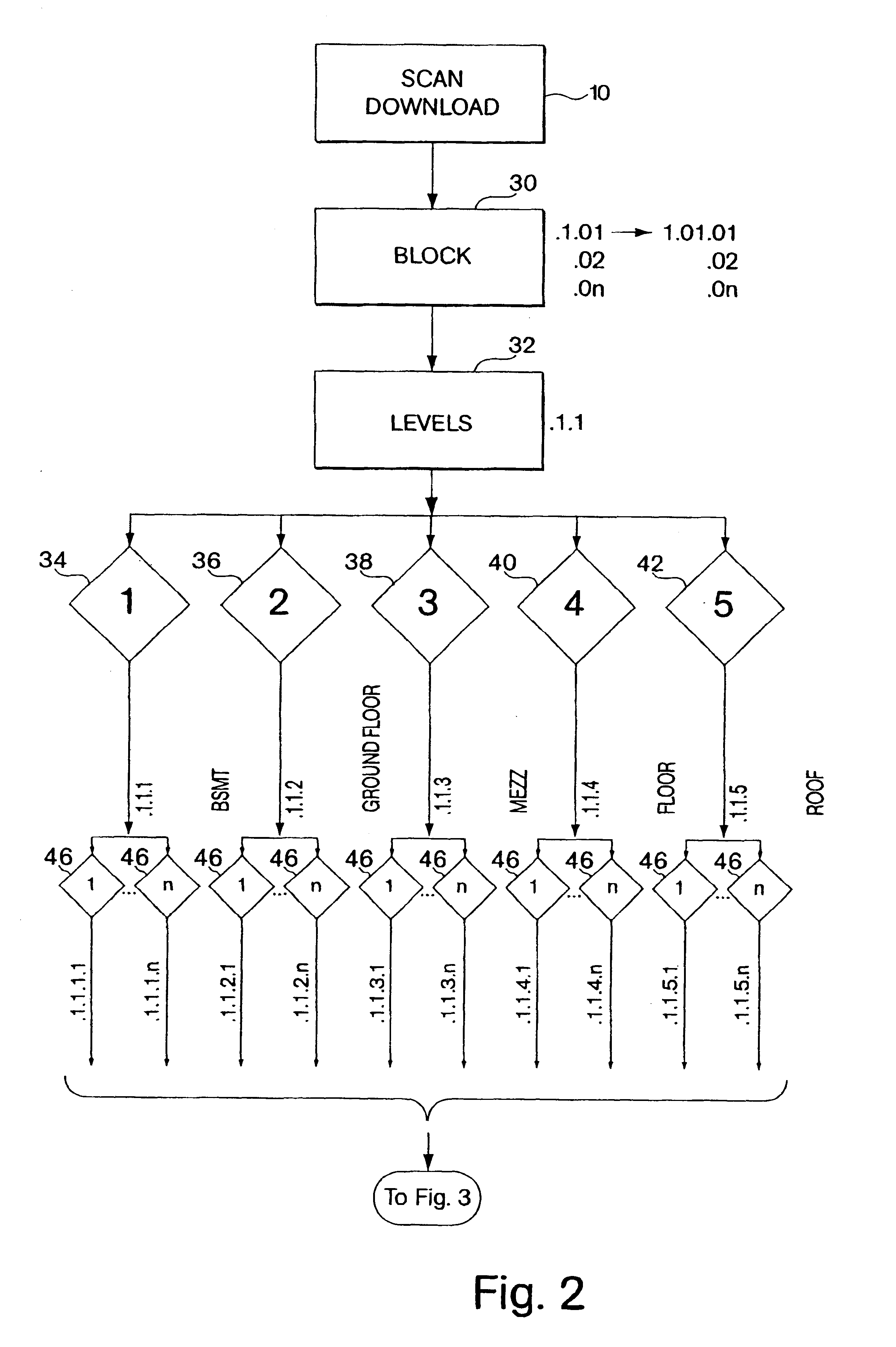
A revised width of the bedroom #4 in block #1 on the first floor is uniquely described by (1.01.1.4.1.1.1.2.1.1.1 .4.1.1.01.02.04.1.02,.03.04.05.1.02.04.0.1.3.01 .1.4.03.1 .3.02.04.01.01).

This is interpreted as follows:

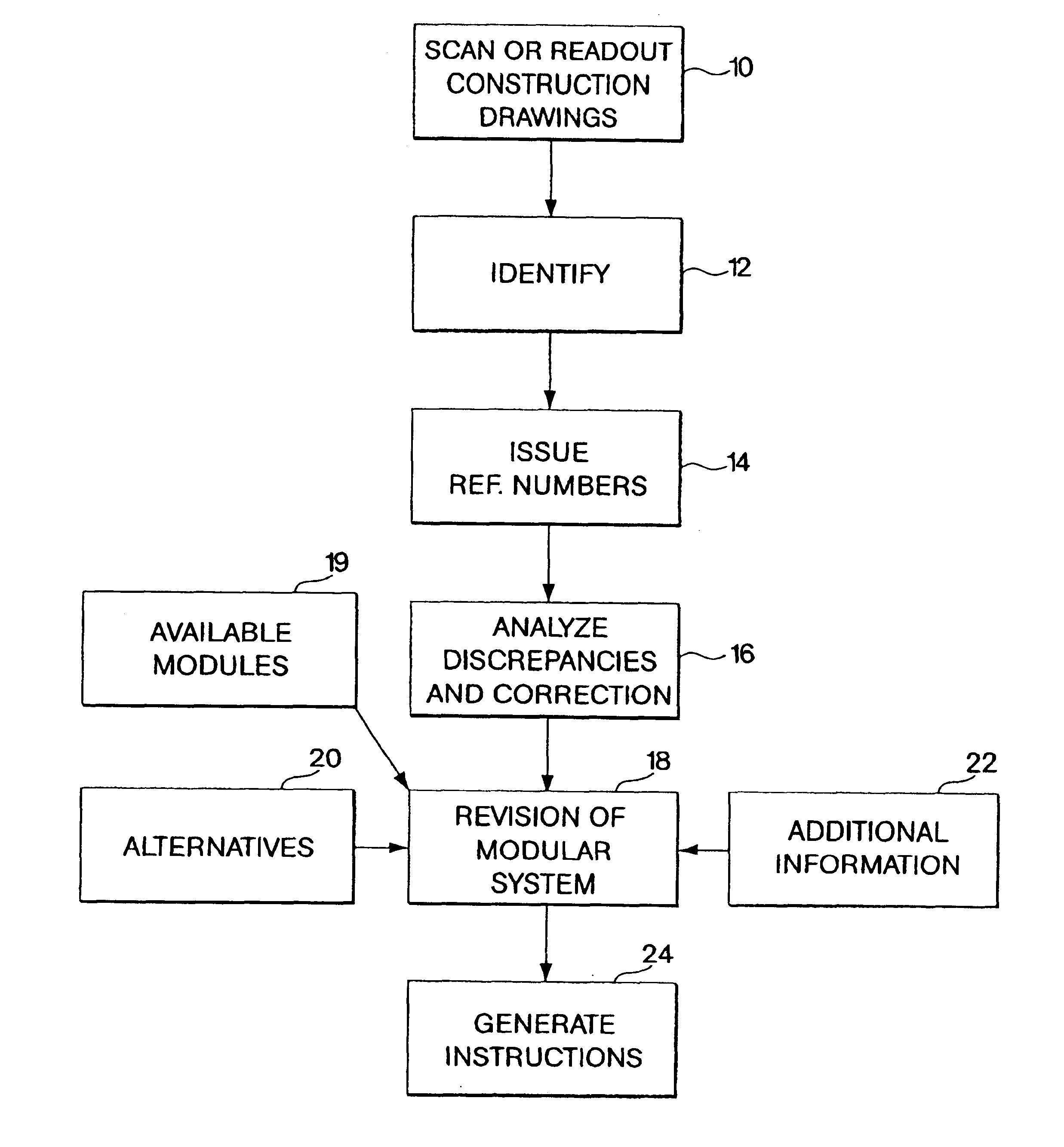
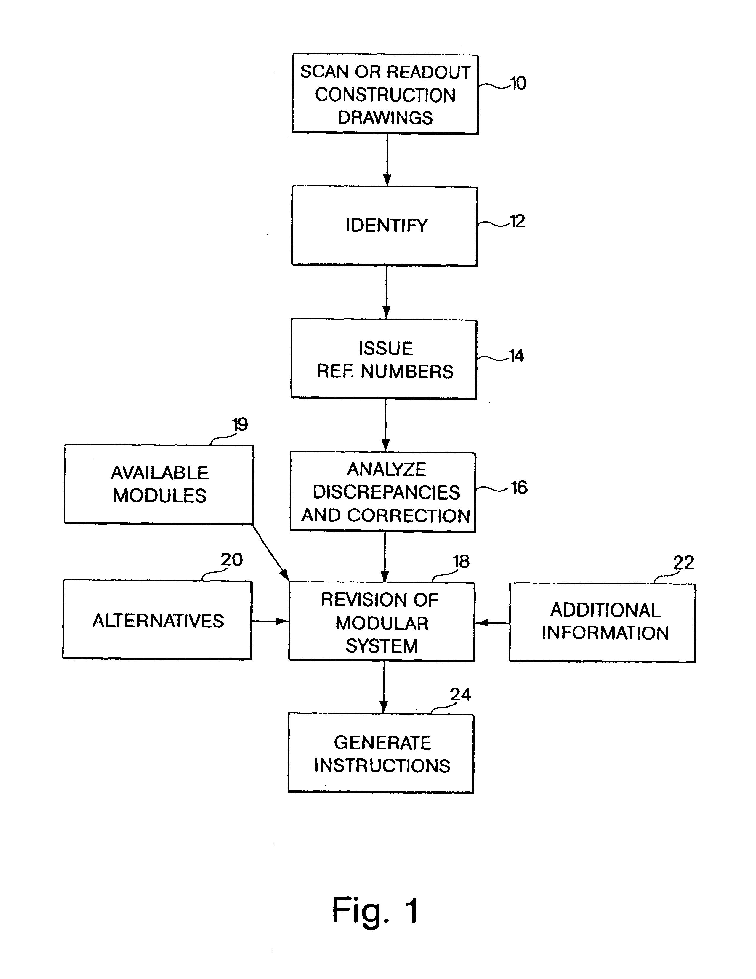
After all of the building elements have been specified in terms of a universal numbering m which will be described hereinafter, each of the elements is analyzed, as illustrated at 16, for discrepancies. Discrepancies can be of a wide range of characteristics, such as errors in dimensions, non-code structures, directional ambiguities, or anything which is either non-code conforming or which is in error in the original construction drawings. Moreover, discrepancies referred to herein also include a lack of synchronization between the various elements, such that when placed together, errors occur. For instance, in the comparison of drawings, one can ascertain that a comer is supposed to be at one location as specified in one drawing, but is a centimeter or two removed in...


PUM


Abstract

A method is provided for specifying parameters for modular formworks from construction documents which define an original structure, in which the construction documents are either scanned or a CAD version is read out. From the scanned drawings or the CAD information, various elements of the structure to be built are identified and selected in an order specific to a particular modular construction system. After identification and selection, reference numerals are assigned for the selected parts or components, with the numbers representing a component of the building such as what floor is intended, walls, ceilings, and other structural components down to the placement of light switches, HVAC vents, drainage, sinks, and plumbing valves. Thereafter, the components defined by the numbering system are analyzed for discrepancies in the original design defined by the construction documents, and modifications are applied to account for dimensional discrepancies, drawing discrepancies and violations of particular building code guidelines. Thereafter, the dimensions of the various building components are revised to conform to the available modules, whereupon instructions are generated as to how to build the original structure from the available modules.

Description

This invention relates to modular building systems, and more particularly to a method for identifying, selecting and modifying information from construction documents describing a structure, using the information to select modular formworks, and to instruct artisans in the erection of the modular formworks for the construction of the structure described by the construction documents.BACKGROUND OF INVENTIONAs illustrated in U.S. Pat. Nos. 5,930,970 and 5,833,872 issued to Patrick Delefevre, a modular building system is described in which various panels, floors, ceilings and other structural components are formed through the utilization of formworks provided by prefabricated apertured panels, channels, beams, and buttressing apparatus which are positioned with mating apertures and plugs to eliminate the time consuming measuring associated with prior formworks. The system described in the above patents permit the forming of concrete so as to provide walls, floors and ceilings as well a...

Claims


Application Information

Patent Timeline
Patent Type & Authority Patents(United States)
IPC IPC(8): E04G17/04E04G17/00E04G17/14E04G11/02E04G9/10E04G11/00
CPCE04G9/10E04G11/02E04G17/001E04G17/002E04G17/047E04G17/14
Inventor DELEFEVRE, PATRICK
Owner DELEFEVRE PATRICK
Why Eureka
Try Eureka