
Method for creating a sleeve member attached to a body portion

a technology of body parts and sleeves, applied in the field of prosthetic sleeves, can solve the problems of increasing pressure stress at dangerous spots, unable to see the stomach through the sleeves, and unable to decide if the sleeves are correctly adapted

Inactive Publication Date: 2002-08-27
CENTRI
View PDF10 Cites 16 Cited by
  • Summary
  • Abstract
  • Description
  • Claims
  • Application Information

AI Technical Summary

Benefits of technology

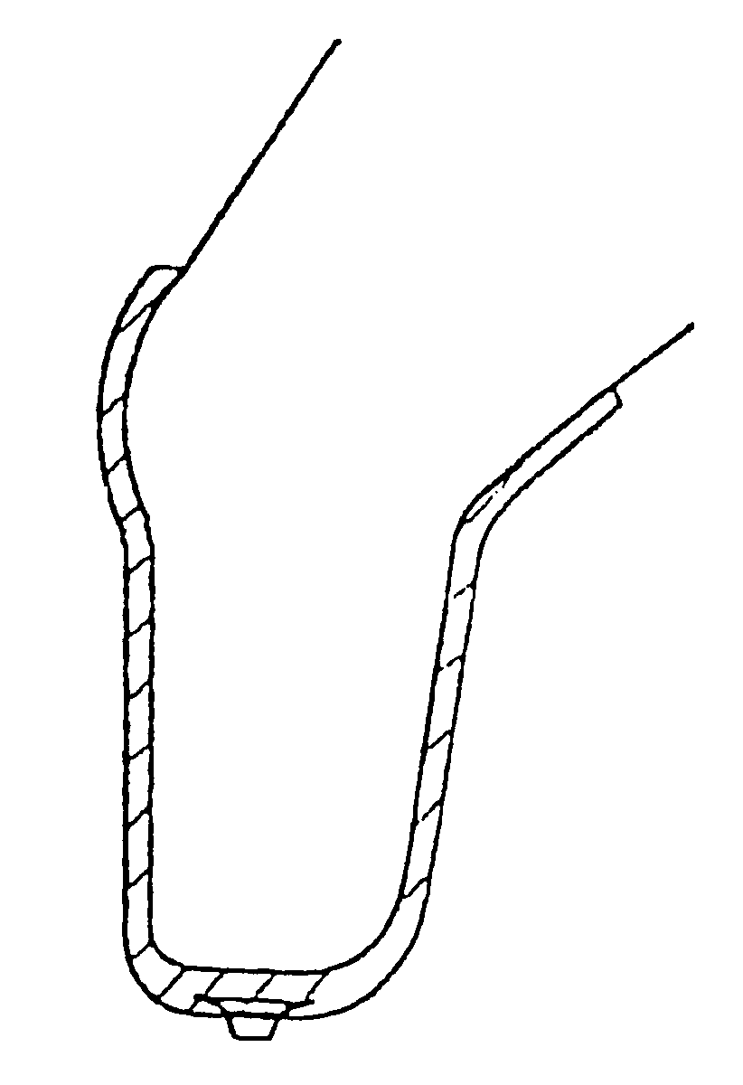
The disadvantages described above are solved by means of a prosthetic sleeve according to the present invention. The new prosthetic sleeve according to the invention constitutes a sleeve member having a conical shape where one end is open and the other completely closed with a somewhat rounded shape. The sleeve member which is made of a thermoplastic elastomer (TPE material) may be formed with heat and is transparent, soft and kind to the skin, which results in that it better can be adapted to any amputation stump.

Problems solved by technology

The disadvantage with such copies is that they are exact only at the time of the plaster casting.
The problem of the rigid sleeve is that it does not follow the changes in volume and what is left of the extremity is soft and sensitive while the sleeve member is hard, which easily results in being chafed if there is not a softer sleeve inside the rigid sleeve.
The drawback is that it must be reinforced by the outer layer of fabric, which implies that the stump cannot be seen through the sleeve.
If the stump cannot be seen through the sleeve it is not possible to decide if the sleeve is correctly adapted.
If a specifically adapted sleeve is incorrectly placed the pressure stress at dangerous spots may be increased.
Furthermore it is not simple to attach a stress-relief to the Alpha sleeve due to the layer of fabric.
The layer of fabric also limits the adaptability, the fabric may only be stretched to a certain limit, and a small uneven stress over the prominences will be introduced.
The problem of this sleeve is that it is not able to be particularly adapted to the amputation stump.
Not only the pressure at these exposed portions will increase, but with this stretching of the sleeve in these more sensitive areas a larger loss of entropy takes place in the sleeve at these areas, in other words the molecule chains are stretched, which in turn decreases their mobility, the soft sleeve becomes harder in the sensitive areas.
Elastic materials harden when they are stretched, but in the case above an uneven hardening will be achieved where the harder portions are placed at the portions being most stressed, which results in discomfort and the user being chafed.
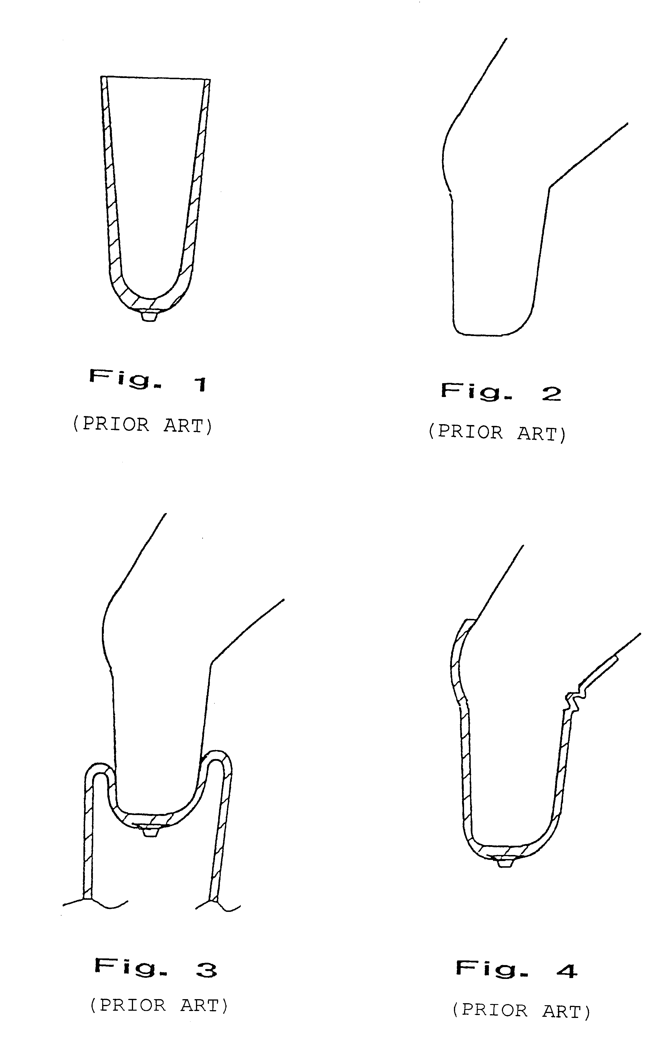
The problem of the frequently seen soft prosthetic sleeves of today is that they fold at the back of the knee when the knee is bent, which results in discomfort and being chafed and, in the worst case, that the flow of blood is obstructed and that a so called stasis condition arises.

Method used


Image

  • Method for creating a sleeve member attached to a body portion
  • Method for creating a sleeve member attached to a body portion
  • Method for creating a sleeve member attached to a body portion

Examples


Embodiment Construction

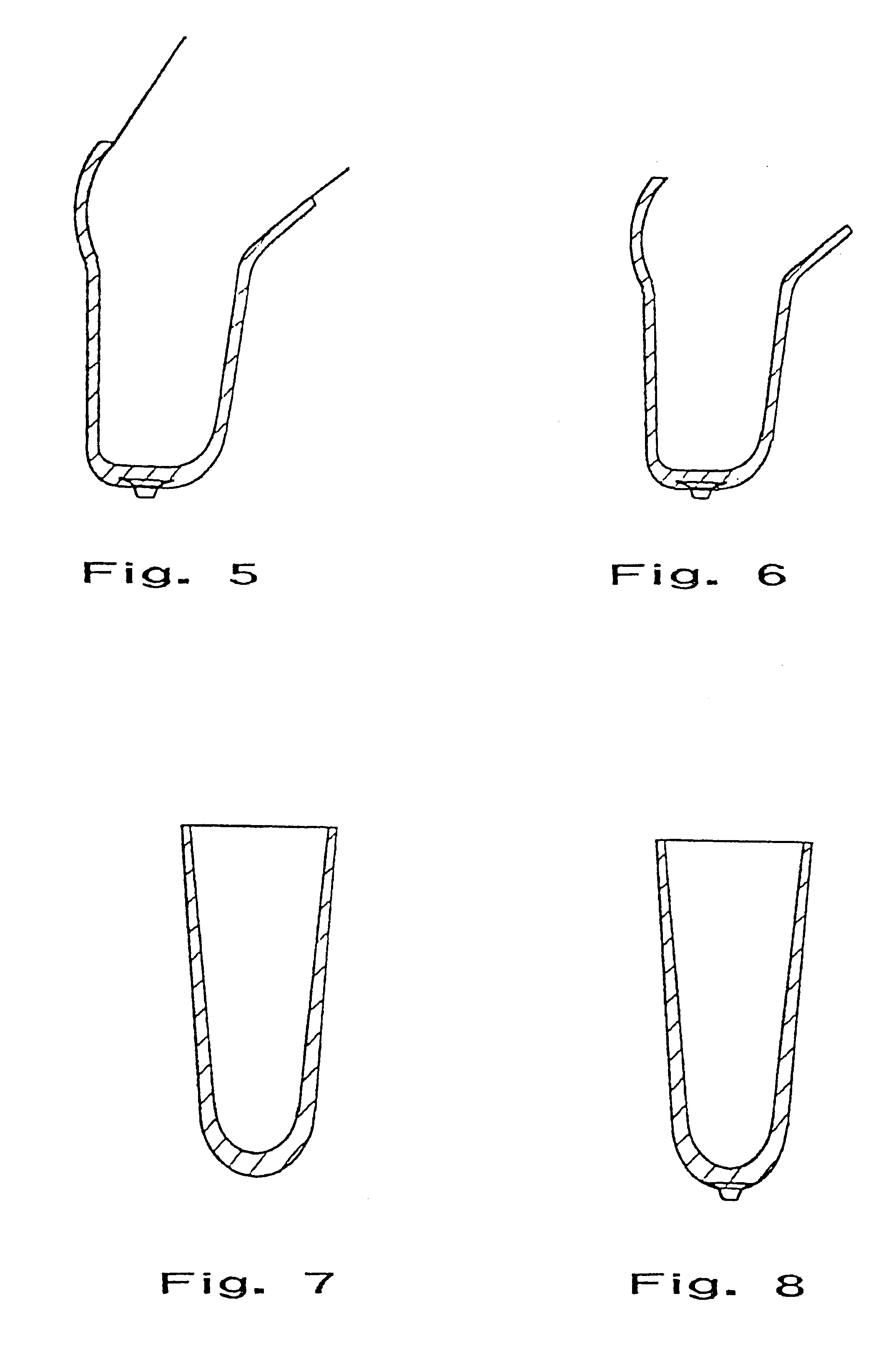
A conical elastic sleeve member similar to the one demonstrated in FIG. 1 is rolled, according to the method of the invention, over a copy of the stump from the amputated extremity. The copy in the example has a shape, demonstrated in FIG. 2, corresponding to a knee with a lower leg stump. The sleeve member according to the invention consists of a thermoplastic elastic material which is characterized by being able to be formed by means of heat. A preferred polymeric material as such is transparent, soft and kind to the skin and elastic and for instance a thermoelastic based on a Styrene-Ethylene / Butadiene-Styrene Block-copolymer (SEBS) and intended for injection moulding and extrudation, as for instance the TPE material DRYFLEX.RTM. 500120 from Nolato Elastoteknik, Torekov, Sweden. The copy of the extremity having the sleeve member of the invention applied is heated in a suitable manner, for instance in an oven. When the sleeve member on the copy of the stump is heated it will form ...


PUM

PropertyMeasurementUnit
Temperatureaaaaaaaaaa
Flexibilityaaaaaaaaaa
Shapeaaaaaaaaaa

Abstract

A method for creating a flexible sleeve member for an amputation stump. The sleeve member is made of a thermoplastic elastic and transparent material. The sleeve member is shaped after a flexed limb, for instance a knee, which makes it easier to avoid foldings of the sleeve, which would otherwise be obtained at the back of the knee when a person wearing the prosthetic device sits down. By means of the sleeve member according to the invention, comfort is improved for a person wearing such a prosthetic device.

Description

The present invention relates to a prosthetic sleeve, and more exactly a sleeve member intended to be adapted to and attached to a body portion like an amputation stump.In connection with amputation of an extremity e.g. a leg, a so called amputation stump is normally kept, that is to say some portion of the amputated extremity is left to serve as an attachment for a suitable prosthesis.A suitably adapted sleeve member is slipped over the remaining stump and constitutes in this way a fastening for the real prosthetic device, which for example may be a foot or a lower leg with foot in case the stump is situated below the knee of a leg. Similarly the prosthesis may be an entire prosthetic leg, whereby a remaining portion of the thigh bone is fitted into a corresponding prosthetic sleeve. In a corresponding way a lower arm or an upper arm prosthesis is attached.Such a sleeve member consists of a conical shape, one end of which is open and the other is completely closed and having a some...

Claims


Application Information

Patent Timeline
IPC IPC(8): A61F2/50A61F2/80B29C67/00B29C70/00B29C70/72A61F2/00
CPCA61F2/5046A61F2/80B29C67/0014B29C70/72A61F2002/30065A61F2002/3009A61F2002/3021A61F2002/30217A61F2002/5053A61F2210/0071A61F2230/0067A61F2250/0091B29K2021/003B29K2995/0026B29L2031/7532
Inventor HELLBERG, KENNET
Owner CENTRI
Learn More