Retaining structure for industrial console

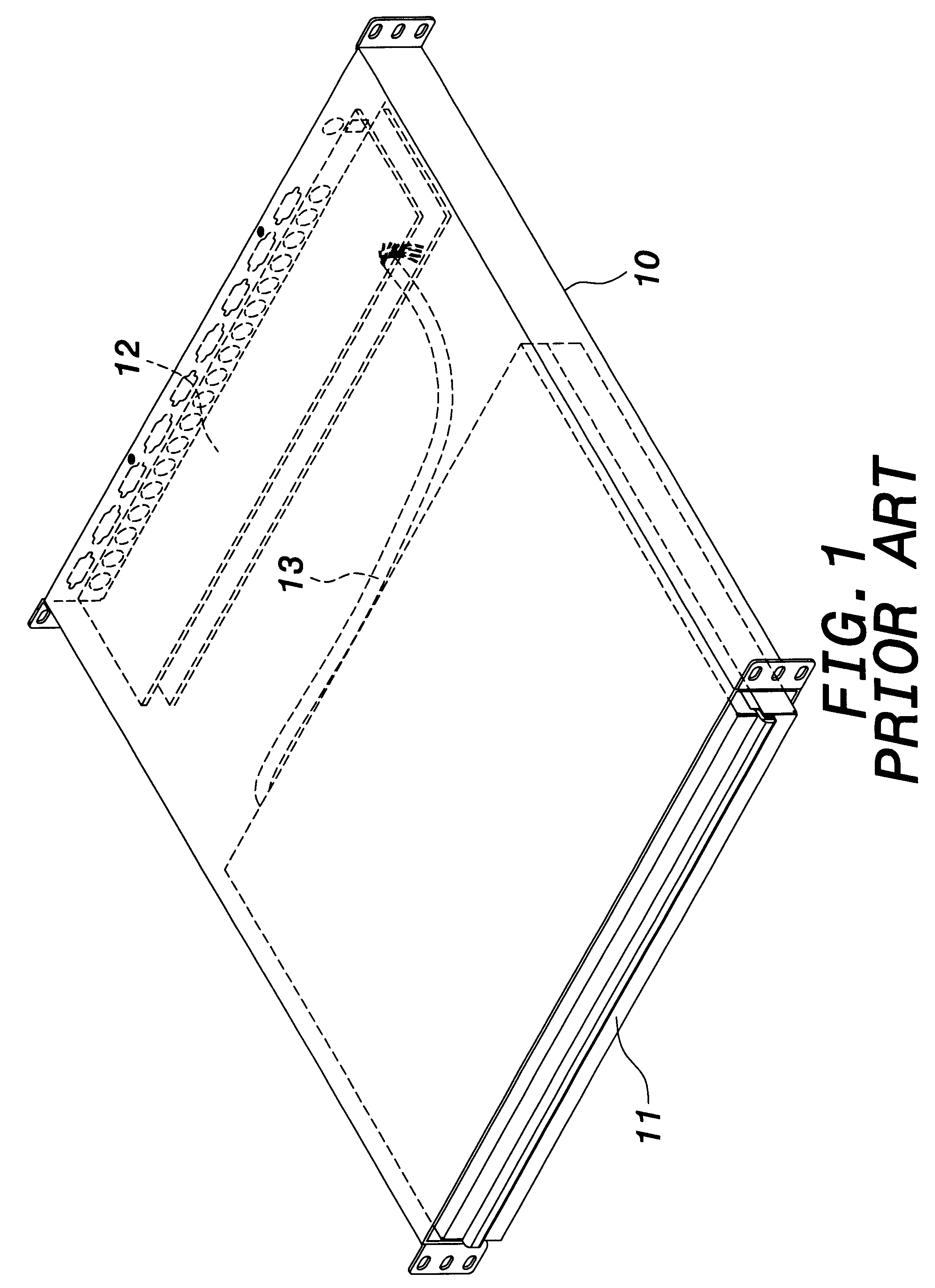
a technology for industrial consoles and retaining structures, which is applied in the direction of electrical apparatus construction details, electrical apparatus casings/cabinets/drawers, furniture parts, etc., can solve the problems of considerable cost waste in the provision of operative modules 11, and achieve the effect of convenient and flexibl

Inactive Publication Date: 2002-08-27
LIU CHENG KUO
View PDF7 Cites 40 Cited by
  • Summary
  • Abstract
  • Description
  • Claims
  • Application Information

AI Technical Summary

Benefits of technology

To achieve above object, the present invention provides a retaining structure for industrial console having at least two sliding rails and two sliding plates slidably arranged on both sides of two brackets such that the brackets can be adapted to fit industrial rack of various sizes. The two brackets are further assembled with a supporting horizontal bar and two sliding grooves such that an operative module and an optional function module can be detachably arranged on both sides of the brackets. The assembling and detaching of the inventive retaining structure is very easy and flexible.

Problems solved by technology

The provision of the operative modules 11 wastes considerable cost.

Method used


Image

  • Retaining structure for industrial console
  • Retaining structure for industrial console
  • Retaining structure for industrial console

Examples


Embodiment Construction

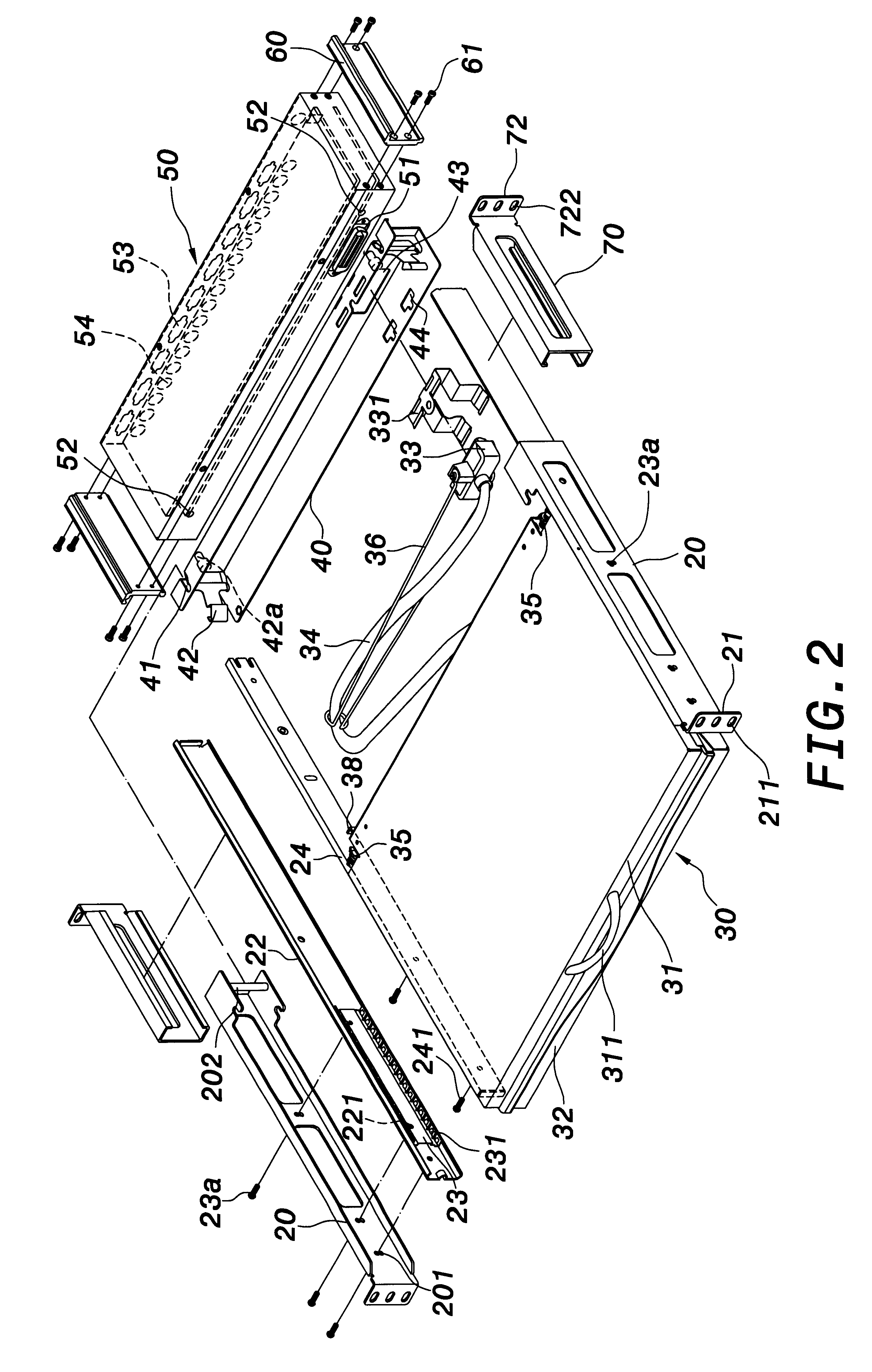
With reference now to FIGS. 2 to 10, the present invention is intended to provide a retaining device for industrial console for industrial rack of various sizes. The retaining device comprises two brackets 20, two sliding rails 22, two sliding plates 23, two sliding shafts 24, an operative module 30, a supporting horizontal bar 40, an optional function module 50, two sliding members 60 and two sliding grooves 70.

The brackets 20 are integrally made of metal and arranged on an industrial rack 80 as shown in FIG. 10. Each bracket 20 has a lug 21 at front side thereof and each lug 21 has a plurality of fixing holes 211, whereby fixing members 81 such as screws, pins or rivets can screwed into the fixing holes 211 to fix the bracket 20 on the industrial rack 80 as shown in FIG. 10.

The bracket 20 has a connection pin 202 at rear side thereof, which is fit into a recess 41 on the supporting horizontal bar 40 as shown in FIG. 5 to link the supporting horizontal bar 40 and the bracket 20. Th...


PUM


Abstract

A retaining structure for industrial console comprises at least two sliding rails and two sliding plates slidably arranged on both sides of two brackets such that the brackets can be adapted to fit industrial rack of various sizes. The two brackets are further assembled with a supporting horizontal bar and two sliding grooves such that an operative module and an optional function module can be detachably arranged on both sides of the brackets. The assembling and detaching of the inventive retaining structure is very easy and flexible.

Description

FIELD OF THE INVENTIONThe present invention relates to a retaining structure for industrial console, especially to a retaining structure for industrial console to fit industrial rack of various lengths.BACKGROUND OF THE INVENTIONAs shown in FIG. 1, the prior art industrial console comprises a frame 10 on an industrial rack (not shown), an operative module 11 and an optional function module 12, wherein the operative module 11 has a plurality of operative buttons and displays (not shown) thereon and the optional function module 12 has a plurality of interfaces (not shown) for user. The operative module 11 and the optional function module 12 are connected by a cable 13 to provide data transmission therein.The operative module 11 and the optional function module 12 are fixed within the frame 10. The frame 10, the operative module 11 and the optional function module 12 are locked to the industrial rack. The relevant interfaces of the optional function module 12 are connected to the opera...

Claims


Application Information

Patent Timeline
Patent Type & Authority Patents(United States)
IPC IPC(8): H05K7/14
CPCH05K7/1421
Inventor LIU, CHENG KUO
Owner LIU CHENG KUO
Why Eureka
Try Eureka