Device for reducing effective radar cross section

a technology for effective radar and cross section, which is applied in the direction of special-purpose vessels, underwater equipment, offensive equipment, etc., can solve the problems of making radar detection more difficult, and reducing so as to reduce the effective radar cross section (rcs) of naval vessels, low space requirement, and low weight

Inactive Publication Date: 2019-01-08
THYSSENKRUPP MARINE SYST GMBH +1
View PDF21 Cites 0 Cited by
  • Summary
  • Abstract
  • Description
  • Claims
  • Application Information

AI Technical Summary

Benefits of technology

[0006]An object of the present disclosure is to provide a device which on the one hand reduces the effective radar cross section (RCS) of a naval vessel and on the other hand has a low space requirement and a low weight, and also can be flexibly retrofitted and is inexpensive. Moreover, it is intended that a substantially neutral or conventional outer appearance of the naval vessel should be made possible in spite of the device.
[0007]This object is achieved by a device for reducing the effective radar cross section (RCS) of a naval vessel comprising a cladding panel, which can be mounted on vessel superstructures or cargo of the naval vessel, the cladding panel being permeable to radar beams, the device also comprising a reflection means, which reflects radar beams, and the reflection means being embedded in the cladding panel and being aligned at least partially inclined with respect to a main plane of extent of the cladding panel.
[0008]The device according to the disclosure has the advantage over the prior art that the reflection means is integrated in the cladding panel, so that the surface of the cladding panel does not comprise any regions with an alignment that is inclined with respect to the main plane of extent. In this way, a neutral or conventional outer appearance of the naval vessel can be retained with regard to form and colouring, and at the same time the radar cross section (RCS) can be reduced, since the radar-reflecting part is partially inclined with respect to the main plane of extent, and consequently the incident radar beams are not reflected directly back to the sender of the radar waves. In other words: the reflection means is formed in particular in such a way that radar beams that are incident on the reflection means along a direction of incidence that is substantially perpendicular to the main plane of extent are reflected by the reflection means in a direction of reflection that deviates from the antiparallel direction of incidence. The integration of the reflection means in the cladding panel also has the advantage that the device can be retrofitted in an easy and flexible way, since this merely requires that the cladding panel is mounted on the corresponding vessel superstructures and / or cargo. The radar echo can even be reduced for cargo in the form of standardized ISO containers by cladding with the device according to the disclosure as a camouflage cap. It is in this way advantageously possible to dispense with the cost-intensive transformation of the geometry of the vessel or the geometry of the cargo, for example into objects with exclusively spherical surfaces.

Problems solved by technology

It is endeavoured to reduce the effective radar cross section (RCS) of naval vessels, in particular when they are for military use, to make detection of the naval vessel more difficult.
Radar detection is thus made more difficult by fewer radar echoes being reflected in the direction of the detecting radar set.
However, these design objectives cannot always be met.
For example, cargo is often transported on modern naval vessels in standardized ISO containers that are securely lashed on deck and, in compliance with their standard, are always cuboidally formed, so that it is not practical to do away with all right angles and create spherical surfaces.
Such cladding elements are comparatively cost-intensive and complex.
A disadvantage of this solution is that a smooth surface cannot be achieved and there is a considerable space requirement.

Method used


Image

  • Device for reducing effective radar cross section

Examples


Embodiment Construction

[0018]In the various figures, the same parts are always provided with the same designations, and are therefore in each case also generally only referred to or mentioned once.

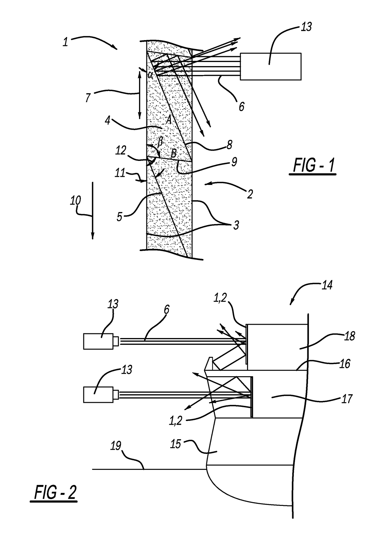
[0019]In FIG. 1, a schematic view of a sectional image of a device 1 for reducing the effective radar cross section (RCS) of a naval vessel 14 according to an exemplary embodiment of the present disclosure is represented.

[0020]The device 1 comprises a cladding panel 2, which takes the form of a rigid or semirigid sandwich panel. For this, the cladding panel 2 comprises two outer layers 3 of glass-fibre reinforced plastic (GRP) and a core 4, which is arranged between the two outer layers 3. The core 4 comprises a foam core, preferably a polyurethane foam (PU). The composite of the outer layers 3 with the foam core provides the cladding panel 2 with a high load-bearing capacity and great stiffness, with at the same time very low weight. Moreover, the cladding panel 2 is permeable to radar beams 6, so that no appre...


PUM


Abstract

A device for reducing the effective radar cross section (RCS) of a naval vessel is proposed, the device comprising a cladding panel, which can be mounted on vessel superstructures or cargo of the naval vessel, the cladding panel being permeable to radar beams, the device also comprising a reflection means, which reflects radar beams, and the reflection means also being embedded in the cladding panel and being aligned at least partially inclined with respect to a main plane of extent of the cladding panel.

Description

CROSS-REFERENCE TO RELATED APPLICATIONS[0001]This application is a 371 U.S. National Stage of International Application No. PCT / EP2015 / 054372, filed Mar. 3, 2015, which claims priority to German Application No. 10 2014 103 601.8 filed on Mar. 17, 2014. The disclosure of each of the above applications is incorporated herein by reference in their entirety.PRIOR ART[0002]The present disclosure is based on a device for reducing the effective radar cross section of a naval vessel which comprises a reflection means for the reflection of radar beams.[0003]It is endeavoured to reduce the effective radar cross section (RCS) of naval vessels, in particular when they are for military use, to make detection of the naval vessel more difficult. Radar detection is based on the principle according to which radar waves are emitted by a radar set as primary waves and are reflected by the object to be detected and returned as secondary waves in the form of radar echoes. The secondary waves are detecte...

Claims


Application Information

Patent Timeline
Patent Type & Authority Patents(United States)
IPC IPC(8): B63G13/02F41H3/00B63G8/34H01Q1/34H01Q15/18
CPCB63G13/02B63G8/34H01Q15/18H01Q1/34F41H3/00B63G2013/027
Inventor EWERS, DIRKDETERMANN, WOLFRAM
Owner THYSSENKRUPP MARINE SYST GMBH
Why Eureka
Try Eureka