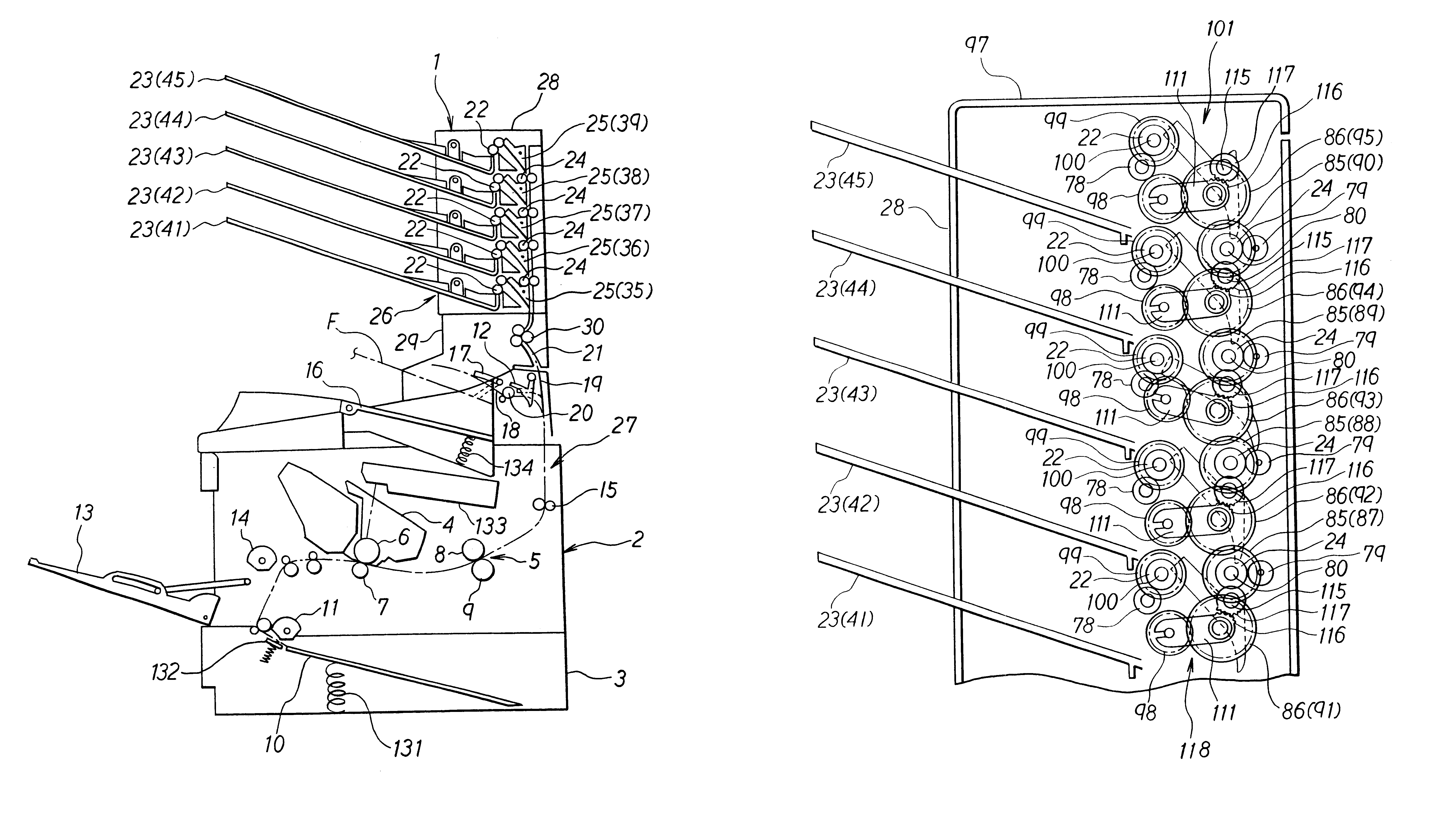
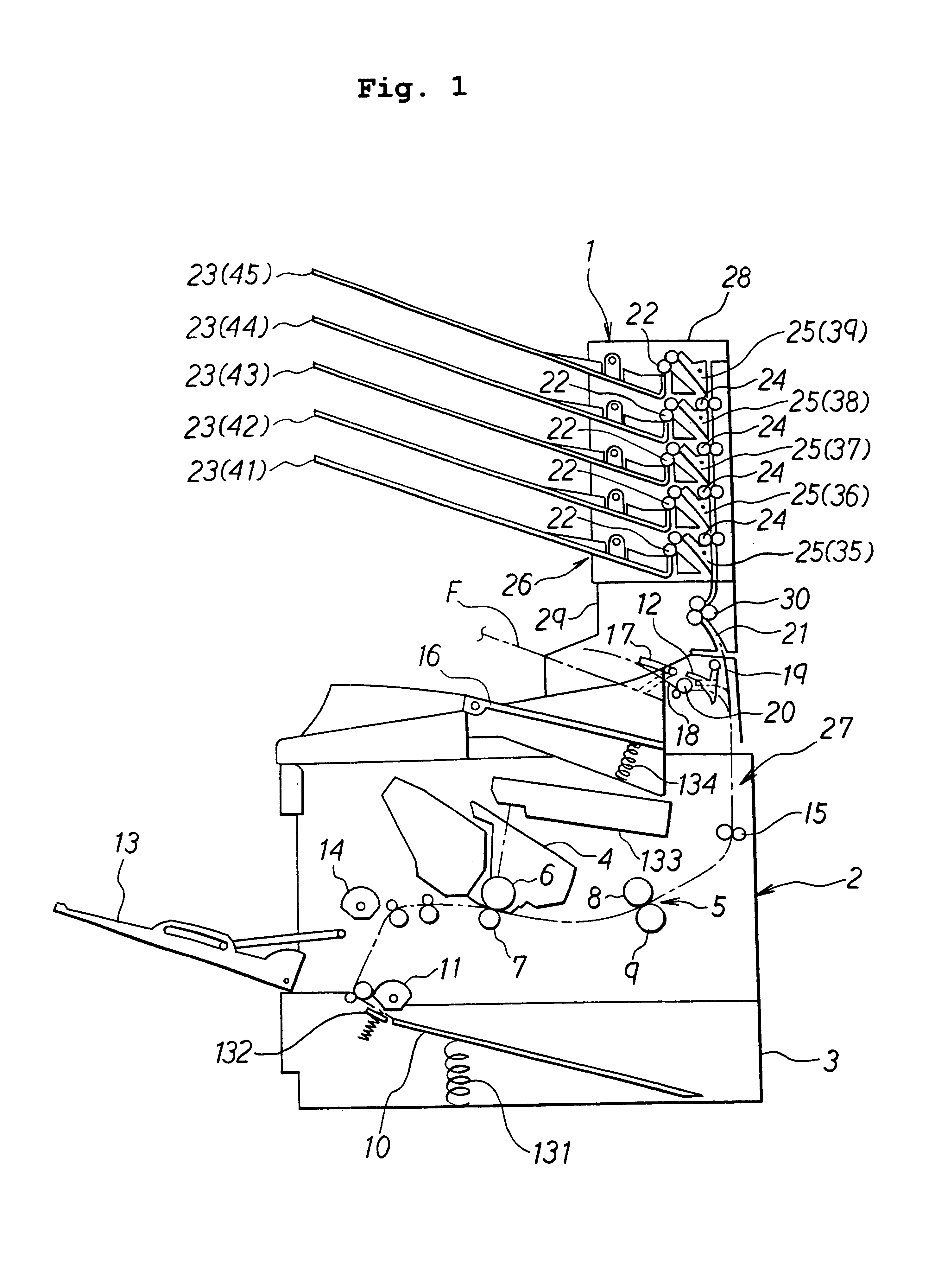
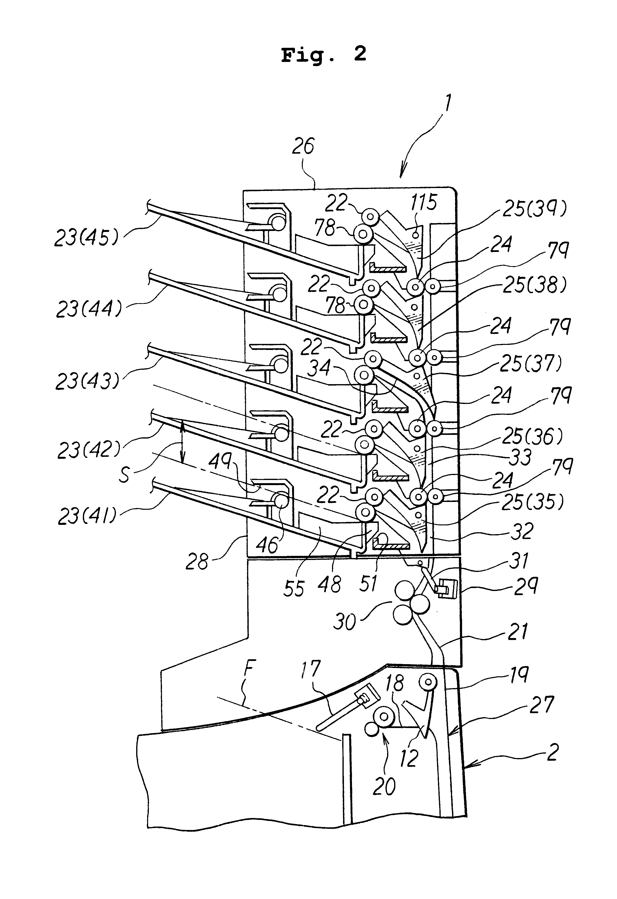
According to the paper sheet discharge apparatus of the present invention, it is unnecessary to move the bin by using a vertical movement mechanism or the like even when a specified bin to be used for storing the paper sheets is changed to another bin. Each of the transport direction-switching units is provided between the transport unit and the delivery rollers associated with the predetermined bin to which the paper sheets should be discharged. Accordingly, the paper sheets, of which the transport direction is switched by the transport direction-switching unit, are reliably discharged to the corresponding bin by the aid of the delivery roller. Therefore, the paper sheets, on which predetermined images are formed, can be sorted and accommodated reliably at a high speed.
According to the paper sheet discharge apparatus as defined in the second aspect, the printed paper sheets are received through the introducing section (for example, an introducing passage 21), and they are transported to the specified discharge means (for example, delivery rollers 22) of the plurality of discharge means by the aid of the transport means (for example, transport rollers 24) and the switching means (for example, switching flappers 25). The transported paper sheets are discharged by the discharge means to the storing unit which is provided corresponding to the discharge means. Therefore, even when the storing unit for storing the paper sheets is changed, it is unnecessary to move the storing unit by using a vertical movement mechanism or the like, in the same manner as in the paper sheet discharge apparatus according to the first aspect. The paper sheets, the transport direction of which is switched by the switching means, are reliably discharged to the corresponding storing unit by the aid of the discharge means. Therefore, the paper sheets, on which predetermined images are formed, can be sorted and accommodated reliably at a high speed.
The paper sheet discharge apparatus according to the second aspect may comprise the plurality of storing units arranged in an aligned state, and it may further comprise a sequential discharge control means (for example, a discharge control program) for switching the switching means so that the paper sheets are successively transported in an order of the storing units aligned in their alignment direction. The sequential discharge control means is operated as follows. That is, when the specified storing unit, to which the paper sheets are transported, have the predetermined amount of paper sheets, the paper sheets are successively transported to another storing unit in the order of the storing units aligned in the alignment direction, and the paper sheets are successively stored in the respective storing units. Accordingly, the paper sheets to be stored are not stored randomly in the plurality of storing units, but they can be stored in a regular state. The paper sheet discharge apparatus according to the second aspect is preferably used in combination with the printing apparatus such as an image-forming apparatus and a printer. The use of the paper sheet discharge apparatus in combination with the printing apparatus makes it possible to smoothly sort and accommodate, at a high speed, the paper sheets discharged from the image-forming apparatus.
According to the paper sheet discharge apparatus as defined in the third aspect of the present invention, the printed paper sheets are received through the introducing section, and they are transported to the specified discharge means of the plurality of discharge means by the aid of the transport means and the transport direction-switching means. The transported paper sheets are discharged by the discharge means to the storing unit which is provided corresponding to the discharge means. The power-transmitting means (for example, a roller-driving gear array 101) for transmitting the power from the driving source to the respective discharge means is operated as follows. That is, all of the discharge means are not driven by commonly transmitting the power from the driving source to the respective discharge means. Instead, the selective transmitting means (for example, a swinging mechanism 118) is successfully used to selectively transmit the power from the driving source to only the specified discharge means which is used to discharge the paper sheets, of the plurality of discharge means. Accordingly, it is possible to diminish the load on the driving source, and it is possible to reduce the driving sound during the operation, as compared with the case in which all of the discharge means are always driven.
In the paper sheet discharge apparatus according to the third aspect of the present invention, the selective transmitting means may comprise a mode-switching means (for example, a delivery roller gear 99) for making
changeover into any one of transmission and cutoff
modes of power from the driving source to the respective discharge means, wherein the mode-switching means is operated while being interlocked with a switching action of the transport direction-switching means. According to the apparatus constructed as described above, the selective transmitting means transmits the power only to the specified discharge means which is used to discharge the paper sheets, of the plurality of discharge means, in accordance with the operation of the mode-switching means, and the
power transmission is
cut off for the other discharge means which are not used to discharge the paper sheets. That is, the simple system to achieve the transmission or the cutoff of the power makes it possible to selectively transmit the power to only the specified discharge means which is used to discharge the paper sheets, of the plurality of discharge means. Further, the mode-switching means is operated while being interlocked with the switching action of the transport direction-switching means. Therefore, it is unnecessary to provide any special apparatus system for switching the mode-switching means. Thus, the power from the driving source can be selectively transmitted in a reliable manner to the discharge means which is used to discharge the paper sheets, by using the simple and convenient system.
The second switching unit may be provided in the discharge apparatus, or in the main printing apparatus body. The provision of the second switching unit in the paper sheet discharge apparatus makes it possible to allow all of the members for determining the discharge direction of the paper sheets to be arranged on the side of the paper sheet discharge apparatus. The provision of the second switching unit in the discharge apparatus makes it possible to simplify the system arrangement on the side of the paper sheet discharge apparatus.


