Restraining module for a cutter of a printer

a technology of a restraining module and a printer, which is applied in the direction of printing, metal working apparatus, printing mechanisms, etc., can solve the problems of dull cutting edges of the moving blade and the fixed blade, and require replacement or re-sharpening

Inactive Publication Date: 2002-09-10
XAC AUTOMATION
View PDF6 Cites 50 Cited by
  • Summary
  • Abstract
  • Description
  • Claims
  • Application Information

AI Technical Summary

Benefits of technology

The object of the present invention is to provide a restraining module for a cutter of a printer overcoming the problems of the prior art as described above and being able to prevent from damaging the fixed or moving blade during engagement of the two.

Problems solved by technology

Such an engagement manner thus easily result in damages and scratches of either the moving blade or the fixed blade such that after multiple engagement, cutting edges of the moving blade and the fixed blade may be dull and thus require replacement or re-sharpening.

Method used


Image

  • Restraining module for a cutter of a printer
  • Restraining module for a cutter of a printer
  • Restraining module for a cutter of a printer

Examples


Embodiment Construction

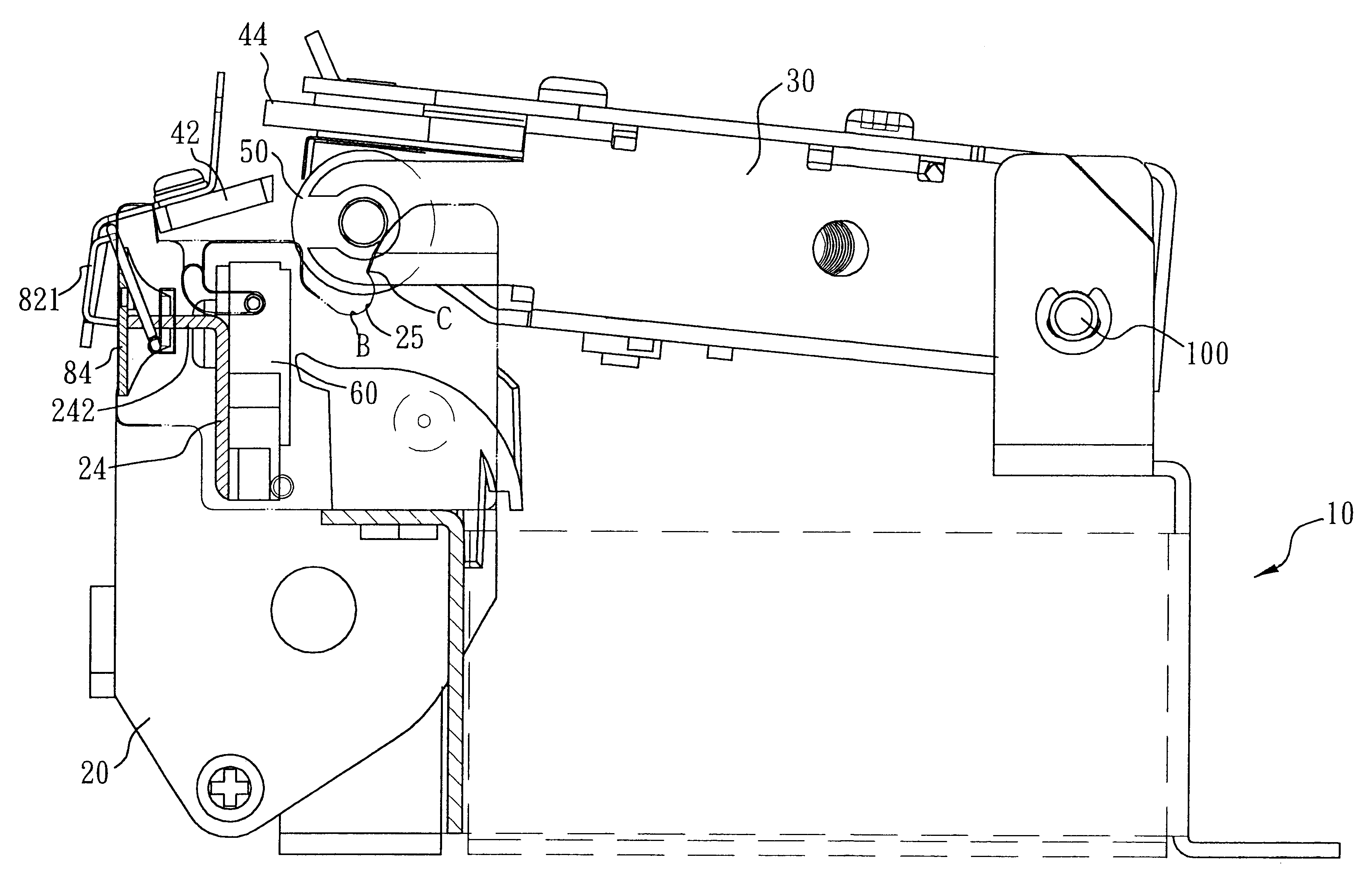
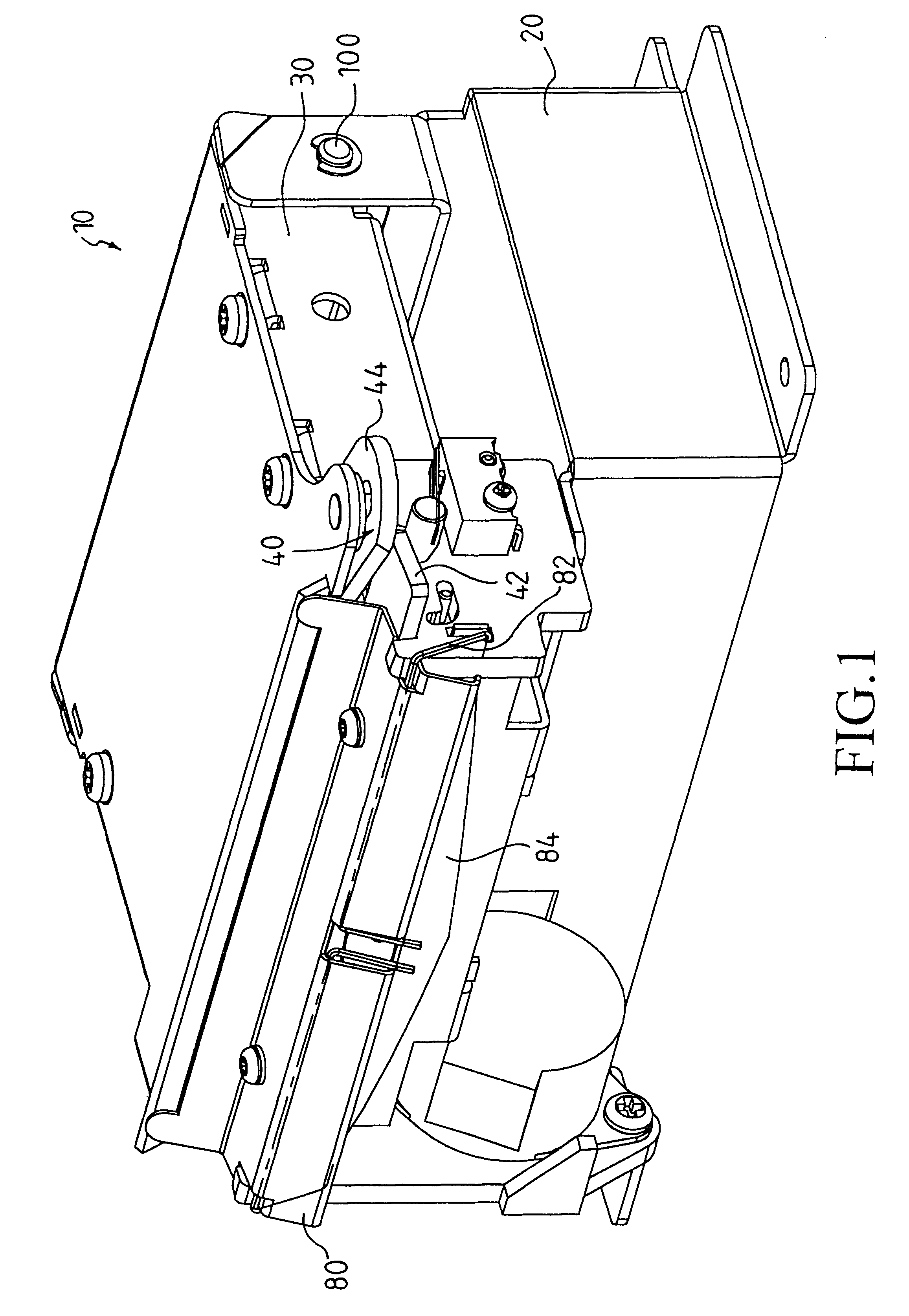
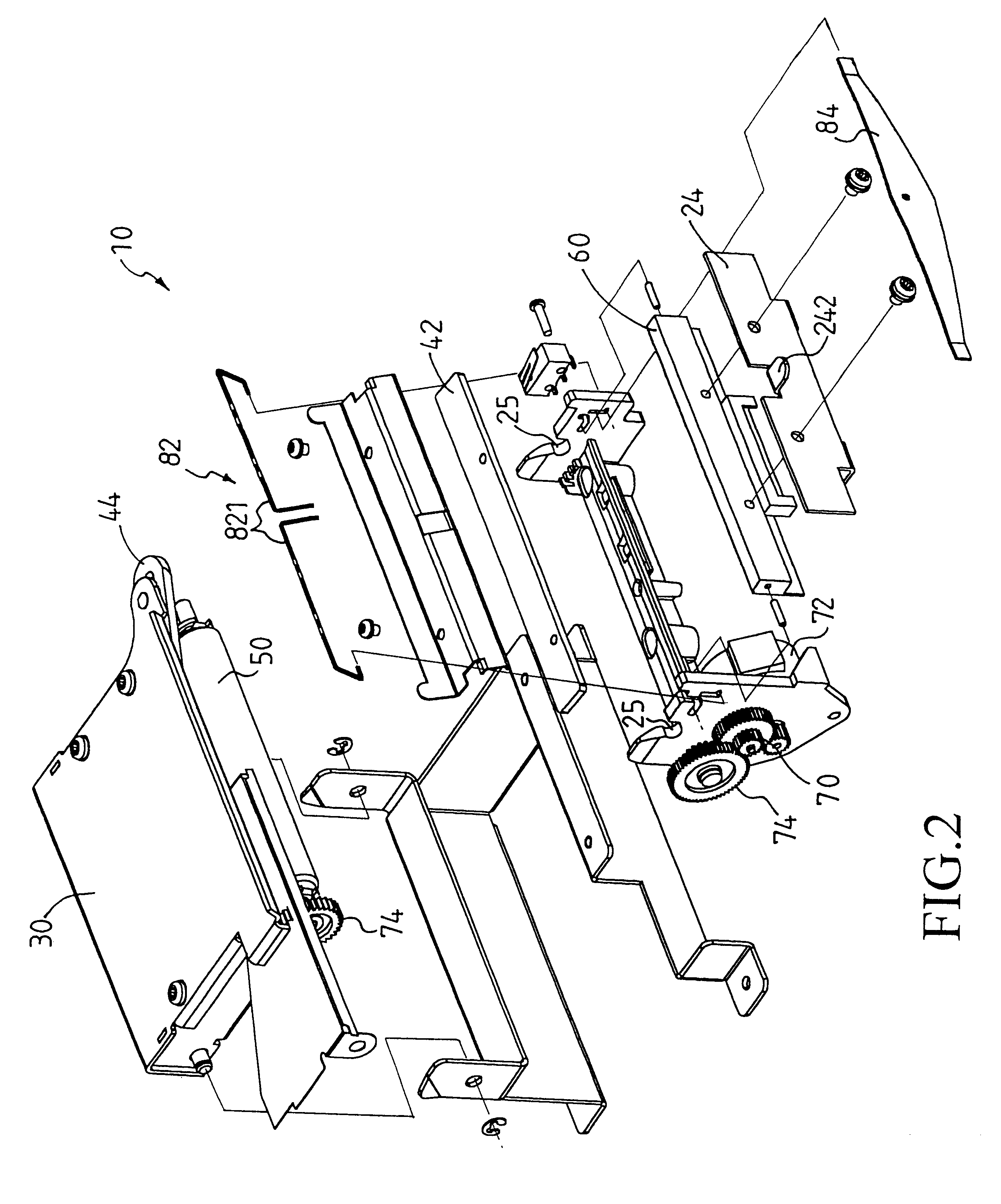
FIG. 1 is a perspective view showing the printing mechanism 10 at its closed position. FIG. 2 is an exploded, perspective view showing the printing mechanism 10 of FIG. 1.

As shown in FIG. 1, the printing mechanism 10 includes a fixed chassis 20 to be mounted on a printer, the fixed chassis having a first edge and a second edge each having opposing ends; a moving chassis 30, having a first edge and a second edge each having opposing ends; a cutter 40; a paper drive roll 50; a thermal head 60; and driving means 70. The second edge of the fixed chassis 20 is pivotally mounted to the second edge of moving chassis 30 via a pivot 100 such that the moving chassis 30 is engageable with the fixed chassis 20 between an open position that is disengaged from the fixed chassis 20, and a closed position that is engaged with the fixed chassis 20, as shown in FIG. 1.

The cutter 40 includes a fixed blade 42 mounted at first edge of the fixed chassis 20, and a moving blade 44 being pivoted to a pivot ...


PUM

PropertyMeasurementUnit
L-shapeaaaaaaaaaa
angleaaaaaaaaaa
forceaaaaaaaaaa

Abstract

Disclosed is a printer having: a fixed chassis mounted thereon; a moving chassis being engageable with the fixed chassis between an open position and a closed position; a cutter including a fixed blade and a moving blade; a paper drive roll; a thermal head; and driving means driving the paper drive roll to subject paper rolling along a paper path formed between the thermal head and the paper drive roll, and the fixed blade and moving blade; wherein the thermal head is in a path of the paper drive roll and wherein the moving blade urges the fixed blade towards the fixed chassis when the moving chassis is at the closed position, and a restraining module for maintaining an appropriate gap between the fixed blade and the moving blade when the moving chassis is engaging the fixed chassis.

Description

The present invention relates to a printer suitable, for example, for use with electronic cash registers used in point-of-sale (POS) systems and relates, more particularly, to a printer comprising a restraining module for its cutter having a moving blade and a fixed blade so as to maintain an appropriate gap between the moving blade and the fixed blade when the printer moving is approaching the closed position thereby allowing smooth engagement of the fixed and moving blades.BACKGROUND OF INVENTIONPrinters used in point-of-sale (POS) systems generally print to rolled paper as the recording medium using a thermal head or other type of print head, and comprise a cutter to cut the printed paper to obtain a sales receipt that can be handed to the customer.Typical of the various cutters employed in such printers are cutters that cut the paper by pushing a cutting blade perpendicularly against the paper as described in JP-A-238970 / 1994, and cutters that cut the recording paper using a fix...

Claims


Application Information

Patent Timeline
Patent Type & Authority Patents(United States)
IPC IPC(8): B26D1/30B26D1/01B41J11/70B26D5/02
CPCB26D1/305B26D5/02B41J11/70Y10T83/8785Y10T83/8854Y10T83/8749Y10T83/885
Inventor ROBINSON, CARL WESLEY
Owner XAC AUTOMATION
Why Eureka
Try Eureka