Fairing arrangement for an aircraft

Inactive Publication Date: 2002-09-17
AIRBUS OPERATIONS LTD
View PDF8 Cites 33 Cited by
  • Summary
  • Abstract
  • Description
  • Claims
  • Application Information

AI Technical Summary

Benefits of technology

By providing a seal which is effective primarily over the normal operational range of the aileron, the service life of the seal can be extended.
By arranging for one of said overlap parts to provide a sealing surface which extends substantially in the direction of the path of movement of the control surface, any significant deflection of one or both overlap parts, usually in a direction normal to the direction of control surface movement, during movement of the control surface over the normal operating range can be minimised if not avoided altogether which is of considerable advantage from the point of view of durability. Moreover, as the sealing surface does not have to seal outside the normal operational range of control surface movement in one direction of movement, it can be made smaller in the fore-and-aft direction which is helpful at least from the point of view of maintaining aerodynamic shape
In a preferred embodiment, one of the overlap parts comprises a sealing element which is preferably flexible and made, for example, from a fabric, rubberised or plastics material. The use of a flexible sealing element is useful in that it can effectively take up tolerances between the overlap parts to minimise or eliminate any gap therebetween. The sealing element may make contact with the other overlap part at least over part of the normal operational range of movement of the control surface. Preferably, the sealing element provides the said sealing surface.
Preferably, the sealing element is mounted on its associated fairing portion via a joint which minimises discontinuity between the outer surface of the fairing portion and the sealing element. The joint may be a halving-type joint. Conveniently, the sealing element may be carried by the first fairing portion.
Preferably, the angle of taper varies over the length of the sealing surface. Such an arrangement further helps to maintain the seal where movement of the control surface takes place about a hinge line arranged at an angle to the direction of flight.

Problems solved by technology

Long flexible seals are not ideal from the point of view of maintaining aerodynamic shape.
Moreover, the deflection which is experienced makes the seals prone to fatigue and hence they have a short life in service which, again, is not ideal.
Also, such long seals tend to experience a substantial amount of deflection particularly when the control surface is at an extremity of movement, for example where the ailerons droop to, say, -30.degree. from a straight and level flight position when the aircraft is standing idle.
This is not ideal, aerodynamically.
Again this is undesirable, aerodynamically, owing to induced drag.

Method used


Image

  • Fairing arrangement for an aircraft
  • Fairing arrangement for an aircraft
  • Fairing arrangement for an aircraft

Examples


Embodiment Construction

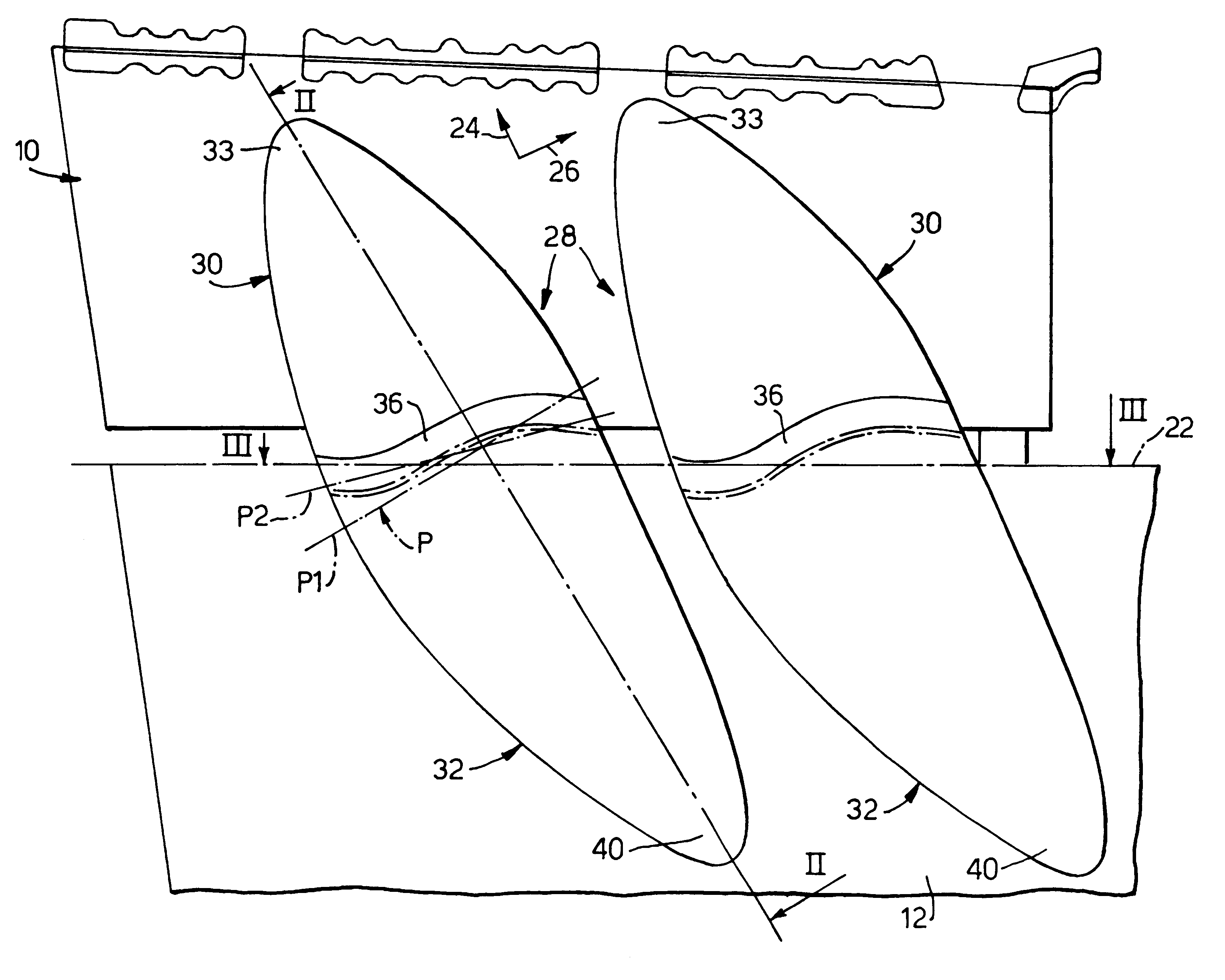
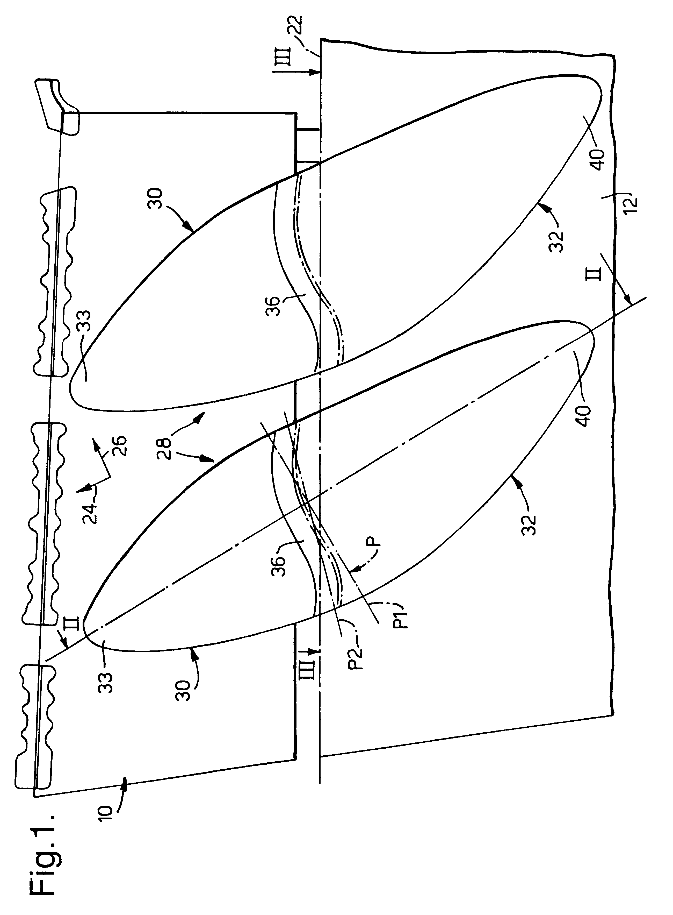
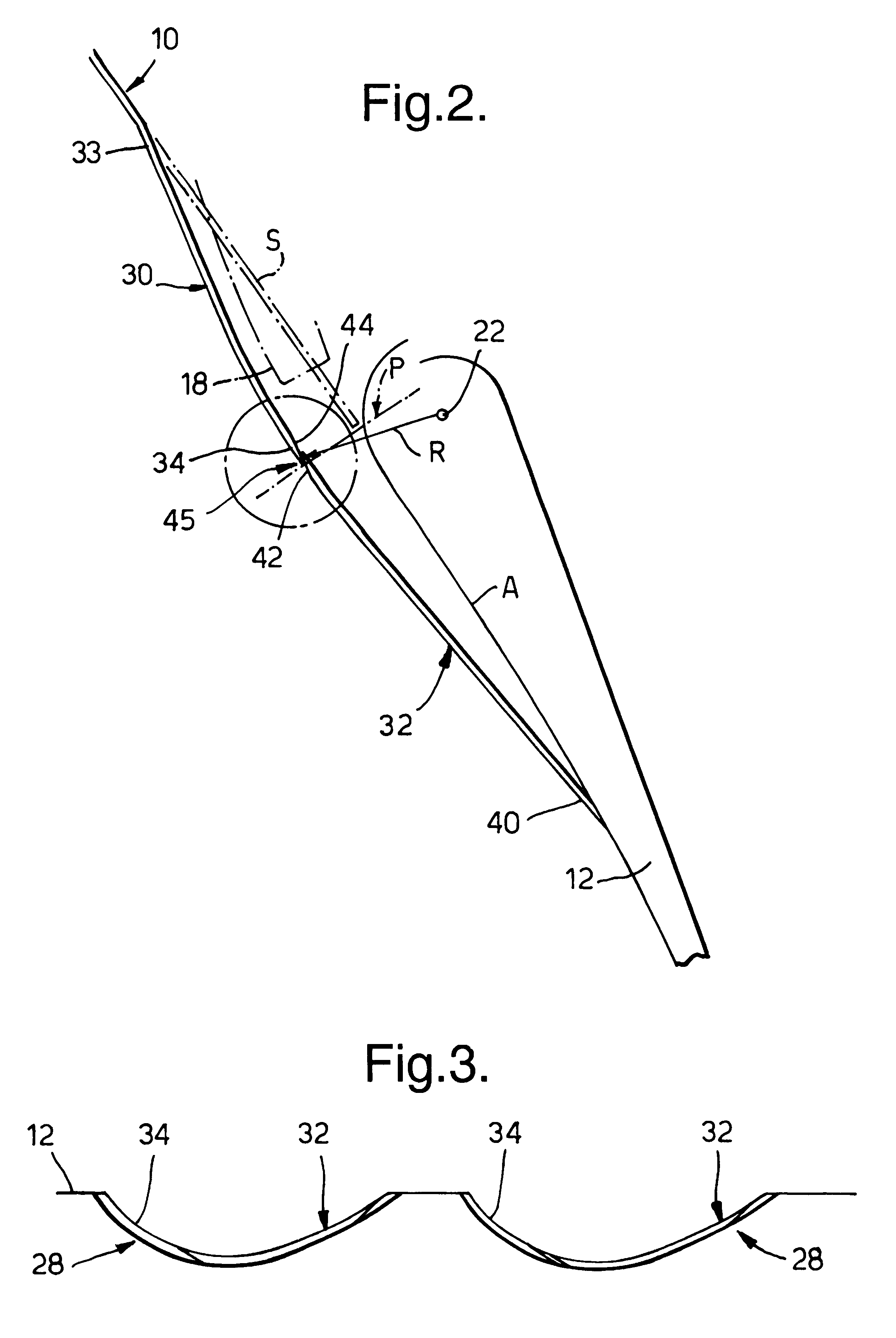
Referring to FIGS. 1 to 4, an aircraft wing 10 carries an aileron 12 on brackets 14 (FIG. 4). Two aileron actuators 18 are mounted on the wing 10 in known manner and transmit movement to the aileron 12 through the brackets 14. Hinge parts 16 and further hinge parts 20 together define an aileron hinge line 22. The aileron 12 is attached to the hinge parts 20. FIGS. 1 and 4 carry directional arrows 24, 26 which are marked "FORWARD" AND "OUTBOARD". The forward arrow 24 indicates the direction of flight of the aircraft (also referred to herein as the fore-and-aft direction) . FIGS. 1 and 4 show the way in which two fairing arrangements 28 extend in the fore-and-aft direction.

Each fairing arrangement 28 comprises a first fairing portion 30 mounted on the wing 10 and a second fairing portion 32 mounted on the aileron 12. The first fairing portion 30 blends smoothly on to the surface of the wing 10 at a front end 33 and extends to an arcuate cross-section rear edge 34. The rear edge 34 inc...


PUM


Abstract

The fairing arrangement 28 comprises a first fairing portion 32 on a wing 10 and a second fairing portion 34 on an aileron 12 which is mounted on and angularly displaceable with respect to the wing. The fairing arrangement protrudes 28 outwardly of the aerodynamic profile S of the wing to cover part of an actuating device for the aileron. Parts of the first and second fairing portions 32, 34 are arranged to overlap each other to form a seal 45, one of said overlap parts defines an oblique sealing surface 44 which lies substantially in the direction of the path of movement of the aileron 12 over the normal operational range of movement of the aileron. The overlap parts 32, 34 of the first and second fairing portions overlap each other over a normal operational range of the aileron 12 to form the seal 45 but do not overlap to form a seal over the remainder of the range in one of the directions of movement of the control surface.

Description

1. Field of the InventionThe invention relates to a fairing arrangement for an aircraft and is primarily concerned with a fairing arrangement for a control surface such as an aileron for a wing of the aircraft.2. Discussion of Prior ArtControl surfaces of aircraft are frequently operated by means of actuator jacks. The size of the actuator and the geometry of the wing and control surface often lead to the actuator protruding below the lower surface of the wing and a fairing arrangement is required to cover the jack or other actuating device. The present invention is primarily concerned with a fairing arrangement of that kind.Various prior fairing arrangements involving flexible seals between a first fairing portion on a fixed structure such as a wing and second fairing structure on a control surface are described in GB-A-2323576. The seals maintain an aerodynamic profile and help to prevent ingress of debris etc. The seals disclosed are intended to operate over the full range of con...

Claims


Application Information

Patent Timeline
IPC IPC(8): B64C7/00
CPCB64C7/00
Inventor SHARP, KIM
Owner AIRBUS OPERATIONS LTD
Why Eureka
Try Eureka