Double-sided self-adhesive reinforced foam tape

a self-adhesive, foam tape technology, applied in the direction of film/foil adhesives, roofs, synthetic resin layered products, etc., can solve the problems of high scrap loss, high scrap loss, coextrusion process,

Inactive Publication Date: 2002-09-17
SYLVESTER MICHAEL S
View PDF32 Cites 67 Cited by
  • Summary
  • Abstract
  • Description
  • Claims
  • Application Information

AI Technical Summary

Problems solved by technology

The extra handling of the product needed to complete these multiple steps results in a high percentage of scrap loss.
However, the coextrusion process described in the '922 patent is also characterized by high scrap losses, especially during the start-up phase.
Further, the product suffers from the deformation problems discussed below.
A second problem with traditional foam tapes is they are generally not reinforced.
Thus, during both processing and application, especially if used in longer strips, deformation and stretching of the product can occur.
The deformation also occurs due to the extra handling and constant turning of the product during manufacturing.
This results in a product that can be difficult to handle and provides a less than perfect fit.
The problem with this polyester film-reinforced product is that it is expensive and laborious to produce, and requires the use of UV light to polymerize the foam.
The process also requires the use of a start-up release paper, which is discarded after the foam is polymerized, thus adding to the scrap losses.

Method used


Image

  • Double-sided self-adhesive reinforced foam tape
  • Double-sided self-adhesive reinforced foam tape

Examples


Embodiment Construction

As used herein, parts are parts by weight and percents are weight percents unless otherwise indicated or apparent. When a preferred range such as 5-25 is given, this means preferably at least 5 and, separately and independently, preferably not more than 25. The contents of U.S. patent application Ser. No. 09 / 198,659 filed Nov. 24, 1998 now U.S. Pat. No. 6,190,751 are incorporated herein by reference in their entirety.

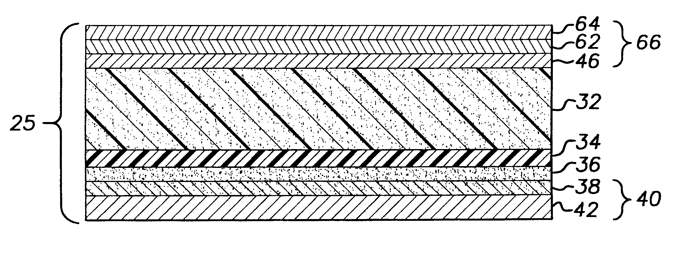
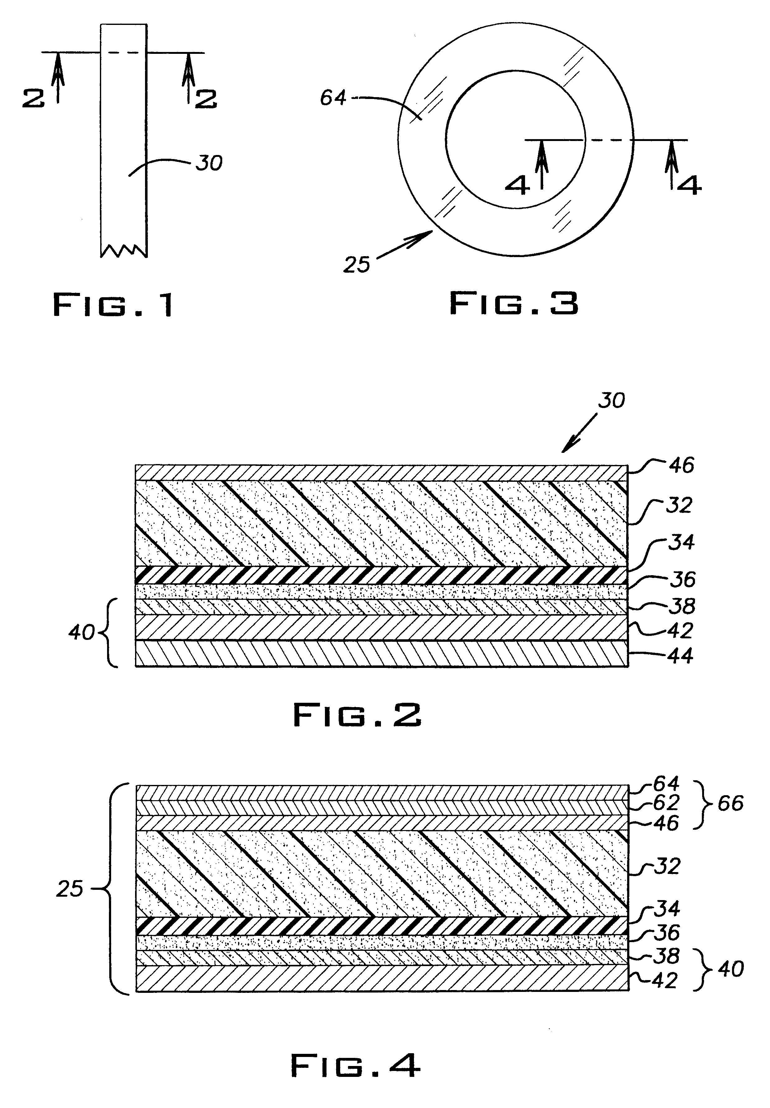
With reference to FIGS. 1 and 2 there is shown a length of self-adhesive reinforced foam tape or mounting tape 30 of the present invention having a top pressure sensitive adhesive (PSA) layer 46.

With reference to FIG. 2 there is shown in cross-section a double-sided self-adhesive reinforced foam tape 30 of the present invention. Tape 30 comprises a release liner 40 comprising release paper 42 having two release (preferably silicone) coatings 38 and 44 which provide release surfaces. Thus release liner 40 has upper and lower surfaces which are release surfaces. The relea...


PUM

PropertyMeasurementUnit
densityaaaaaaaaaa
thickaaaaaaaaaa
lengthaaaaaaaaaa

Abstract

A double-sided self-adhesive reinforced foam tape comprising a release liner having upper and lower surfaces which are release surfaces, a first layer of pressure sensitive adhesive applied to the upper release surface, a layer of flexible polymeric film, preferably polyester film, applied to the first pressure sensitive adhesive layer, a layer of flexible foam, preferably closed cell PVC flexible foam, thermally bonded to the flexible polymeric film layer, and a second layer of pressure sensitive adhesive applied to the flexible foam layer. A length of material for use as a double-sided tape is provided, along with a method of making the length of material. An alternative embodiment, suitable for die-cutting, including a second release liner applied to the second pressure sensitive adhesive layer is provided. The tape may be used in automobiles and other applications.

Description

The invention relates generally to foam tapes and more particularly to a double-sided self-adhesive reinforced foam tape.DESCRIPTION OF RELATED ARTDouble-sided foam tape is well-known. This product is frequently a thick but narrow layer or strip of closed cell plastic flexible foam with layers of pressure sensitive adhesive on opposing surfaces. A release liner is provided on one adhesive surface. The tape is rolled, so that the lower side of the release liner contacts the other adhesive surface. In use, the tape is unrolled and the exposed adhesive surface is adhered to one of the two items that are to be held together. The release liner is then removed, exposing the second adhesive surface.The tape is usually produced by a process starting with a substrate, laminating one side, coating that side with a pressure sensitive adhesive, flipping the product over, and repeating the process again on the other side. The extra handling of the product needed to complete these multiple steps ...

Claims


Application Information

Patent Timeline
Patent Type & Authority Patents(United States)
IPC IPC(8): B29C44/02B29C44/06B32B5/18C09J7/02E06B7/23E06B7/22F16J15/10B32B27/08C09J7/29
CPCB29C44/06B32B27/08C09J7/0289C09J7/0296E06B7/23F16J15/104B32B5/18Y10T428/28B32B2305/022C09J2201/128C09J2400/243C09J2427/006C09J2433/00C09J2467/006Y10S277/921Y10T428/1476Y10T428/1481Y10T428/2839Y10T428/2835Y10T428/1471Y10T428/14Y10T428/2848Y10T428/2813Y10T428/215C09J7/26C09J7/29Y10T428/249982Y10T428/249991Y10T428/249992Y10T428/249976C09J2301/124
Inventor SYLVESTER, MICHAEL S.
Owner SYLVESTER MICHAEL S
Why Eureka
Try Eureka