GPS patch antenna attitude reference method

a reference method and antenna technology, applied in direction finders, instruments, differential interacting antenna combinations, etc., can solve the problems of unsuitable rotation system angular error with respect to stationary axis, inability to provide antennas with the ability to determine the attitude of rotating spacecraft, and inability to achieve the effect of adjusting the angular error of the stationary axis

Inactive Publication Date: 2002-09-17
THE AEROSPACE CORPORATION
View PDF2 Cites 31 Cited by
  • Summary
  • Abstract
  • Description
  • Claims
  • Application Information

AI Technical Summary

Benefits of technology

The invention is directed to the creation and use of an electronic nulling slit antenna pattern for determining the spin axis attitude of a spinning space vehicle. A preferred sensor system includes a GPS receiver, a conventional sum and difference hybrid, and two juxtaposed 1/4 wave patch antennas. The two 1/4 wave patch antennas are placed side by side, separated by an optimum distance, on a lateral surface of a rotating space vehicle. The side by side placement causes an overlapping of the two antenna patterns each of which having a hemispherical pattern having a peak gain at nearly the center position. A conventional hybrid is used to create sum and difference signals from the two patch antennas. The difference signal is created by the hybrid introducing a 180 degree phase shift between the two patches signal creating an electronic null slit, that is, a null in the difference antenna pattern along the plane of symmetry between the patch antennas. This plane of symmetry is referred to as the center plane position. The sum signal provides a peak gain at the center plane position between the antennas. The sum signal is used for conventional GPS signal detection and reception and for computing a navigation solution of the spinning space vehicle. The difference signal is used as a time reference among a plurality of received ...

Problems solved by technology

The cost of such a system can be appreciable.
These patch antennas do not provide an ability for attitude determination of a spinning spacecraft.
However, the angular error is with respect to a stationary axis unsuitable for att...

Method used


Image

  • GPS patch antenna attitude reference method
  • GPS patch antenna attitude reference method
  • GPS patch antenna attitude reference method

Examples


Embodiment Construction

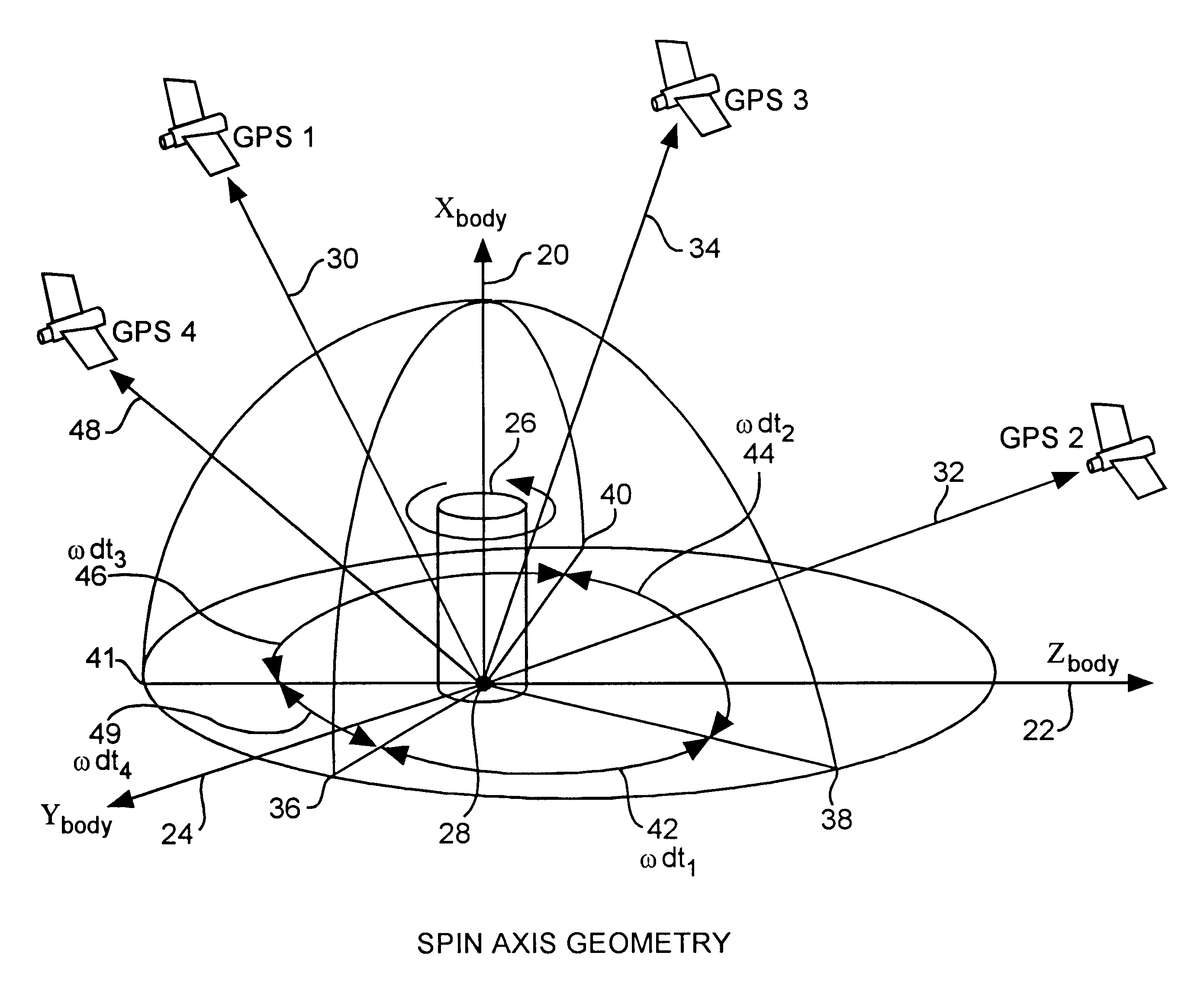
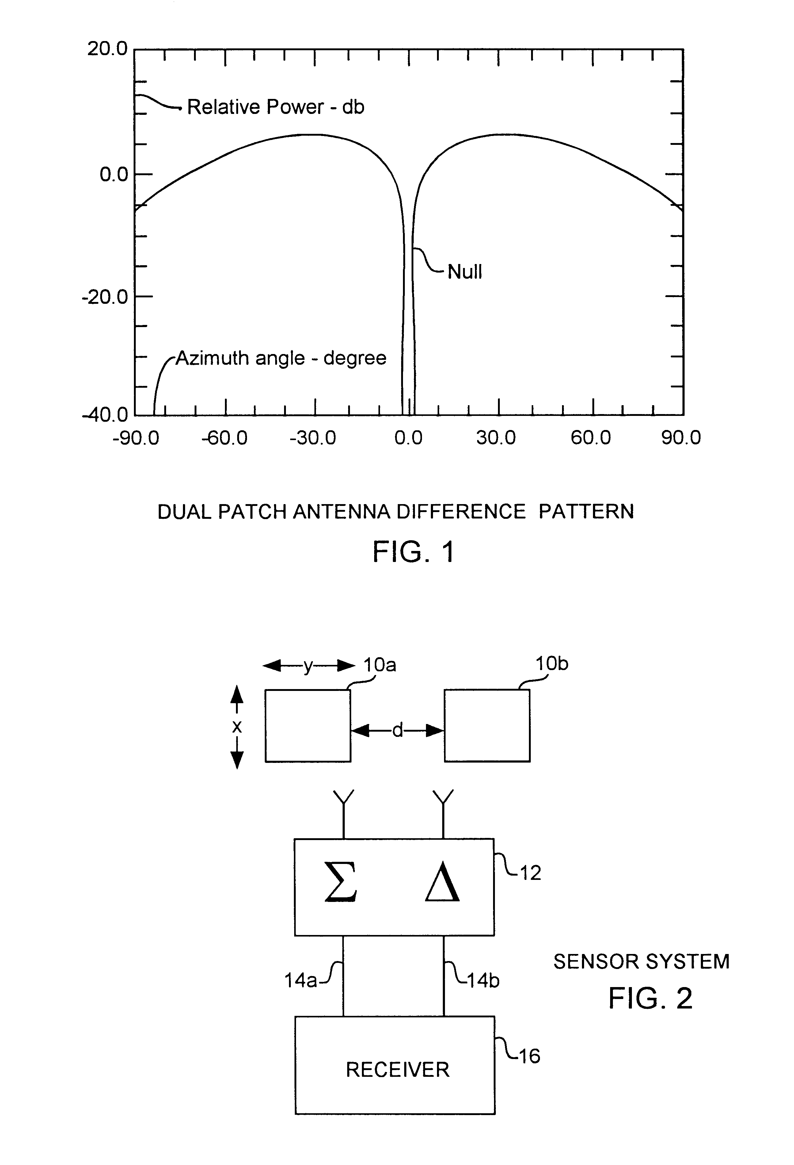
An embodiment of the invention is described with reference to the figures using reference designations as shown in the figures. Referring to FIGS. 1 and 2, a pair of patch antennas 10a and 10b in a sensor system are used to form dual patch antenna sum and difference patterns using a conventional sum and difference antenna hybrid 12 communicating a sum signal 14a and a difference signal 14b to a receiver 16. The pair of patch antennas 10a and 10b each create a hemispherical antenna pattern. With the two patch antennas placed nearly side by side, the two hemispherical antenna patterns are combined using the hybrid 12. A null slit pattern is created by placing two antenna elements side by side with the hemispherical patterns overlapping so that when subtracted from each other using the hybrid 12, the hemispherical pattern of one patch antenna is shifted out of phase and then added to the other hemispherical pattern of the other patch antenna producing a narrow null slit at the center p...


PUM


Abstract

A null slit antenna pattern receives GPS signals from at least three GPS satellites functioning as pseudo stars for spin rate and spin axis attitude determination of a spinning space vehicle in an earth orbit below the GPS satellites.

Description

FIELD OF THE INVENTIONThe invention relates to the field of attitude determination of space vehicle. More particularly, the invention relates to the use of a patch antenna for attitude determination of a spinning space vehicle.BACKGROUND OF THE INVENTIONThe spin axis attitude determination of a spinning space vehicle has been traditionally accomplished by using a combination of sun and earth horizon sensors. A sun sensor measures the sun illumination spike and the elevation angle with respect to the spin axis of the space vehicle. Sun position and elevation information establishes a geometric sun position cone with a half cone angle equal to the elevation angle on which the spin axis lies. A similar earth elevation cone can be constructed based on the earth sensor measurements. The intersection of the sun position cone and earth elevation cone provide the inertial attitude information for determining the spin axis of the rotating vehicle. The cost of such a system can be appreciable...

Claims


Application Information

Patent Timeline
IPC IPC(8): G01S5/02G01S5/14H01Q25/02H01Q21/29H01Q21/00H01Q25/00G01S19/53
CPCG01S3/32G01S19/14G01S19/53H01Q21/29H01Q25/02G01S19/36
Inventor TSENG, GAN-TAIYANG, JO-LIENJOHNS, STEVEN LLOYDWU, CHENG A.
Owner THE AEROSPACE CORPORATION
Why Eureka
Try Eureka