Injection device

a technology of injection device and injection tube, which is applied in the direction of intravenous device, other medical devices, infusion needles, etc., can solve the problem that the previously known solution is therefore somewhat unsuitable for this particular group, and achieve the effect of simple mechanical design

Inactive Publication Date: 2002-09-24
BAYER INTELLECTUAL PROPERTY GMBH
View PDF19 Cites 217 Cited by
  • Summary
  • Abstract
  • Description
  • Claims
  • Application Information

AI Technical Summary

Benefits of technology

The essential object of the invention is to develop generic injection devices in such a way that, whilst having a simple mechanical design, the patient's actions required for handling are reduced to a minimum, in particular the extraction and insertion of the disposable syringe are simplified to such an extent that only minimal requirements are demanded of the (remaining) physical and mental abilities of the patient.

Problems solved by technology

The handling of both these last two injection devices when the disposable syringe is being changed requires, particularly when the two housing parts, together with the reinserted, new ready-made syringe, are brought together accurately in terms of fit and direction, some degree of manual skill which cannot be presupposed in the group, referred to above, of chronically sick, older people; this previously known solution is therefore somewhat unsuitable for this group in particular.

Method used


Image

  • Injection device
  • Injection device
  • Injection device

Examples


Embodiment Construction

The basic design of the injection device according to the invention will be explained first, followed by the individual operating segments within a work cycle.

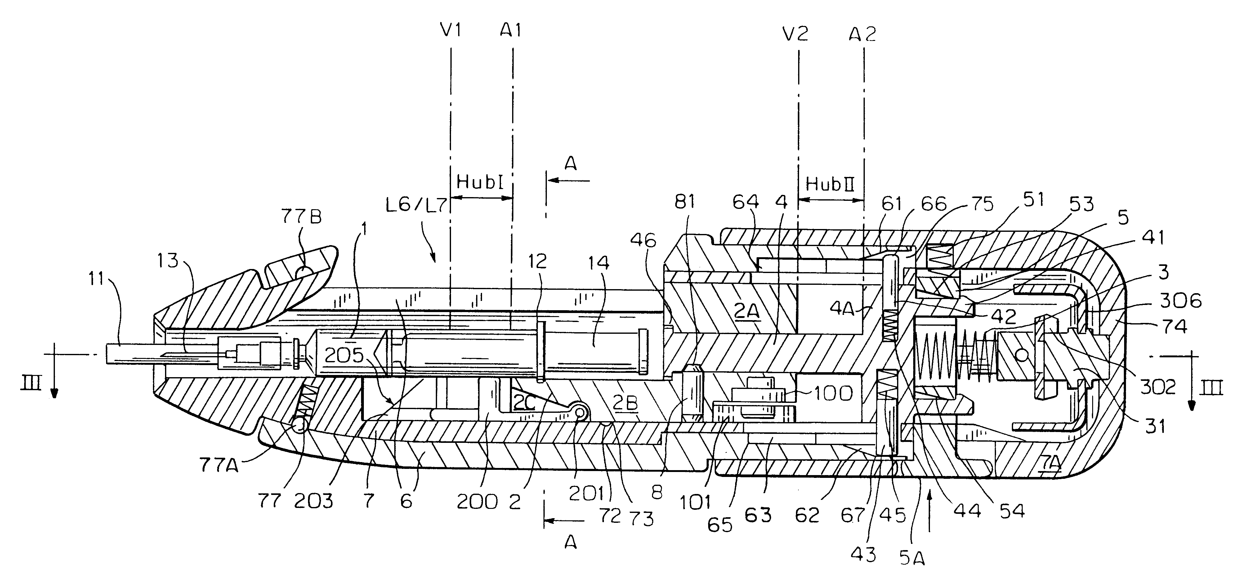
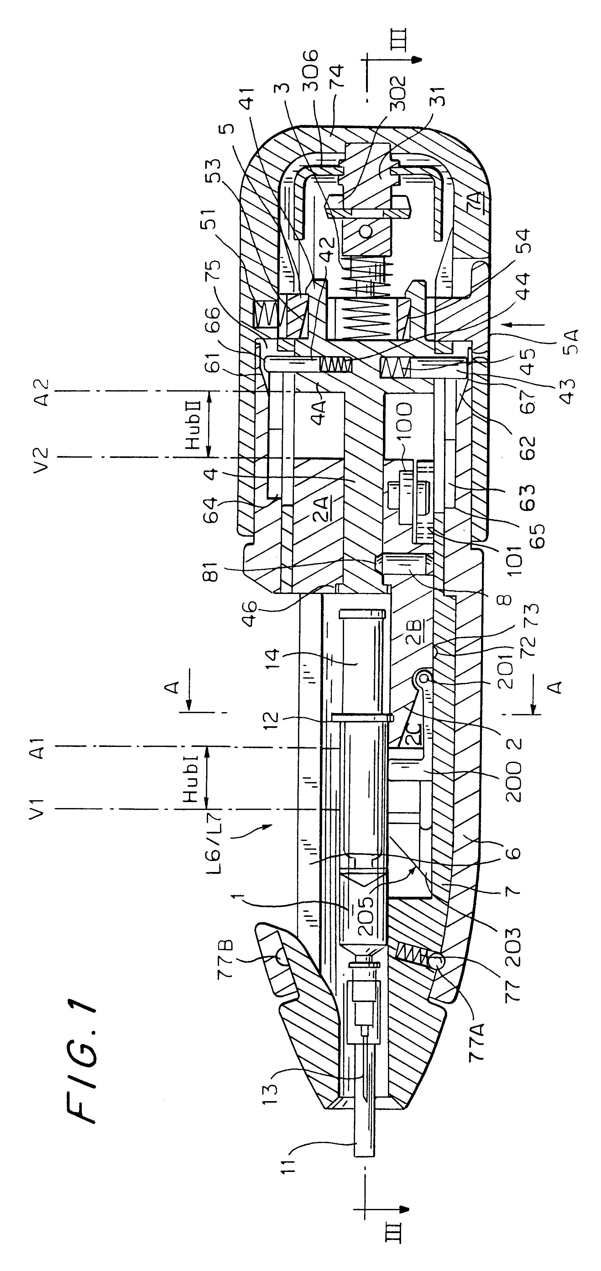
The injection device possesses, as it were as a "mechanical supporting skeleton", a housing 7, the front portion 7C of which tapers conically where the needle 13 of the syringe 1 emerges, said housing being designed essentially cylindrically in its middle portion 7B and merging into a rear, caplike handling portion 7A with a housing rear wall 74 having an annular groove 75. The longitudinal axis F of this housing 7 forms the longitudinal axis, that is to say that axis 30 in which the syringe 1 is held and in which the essential movements and control operations for injection also consequently take place.

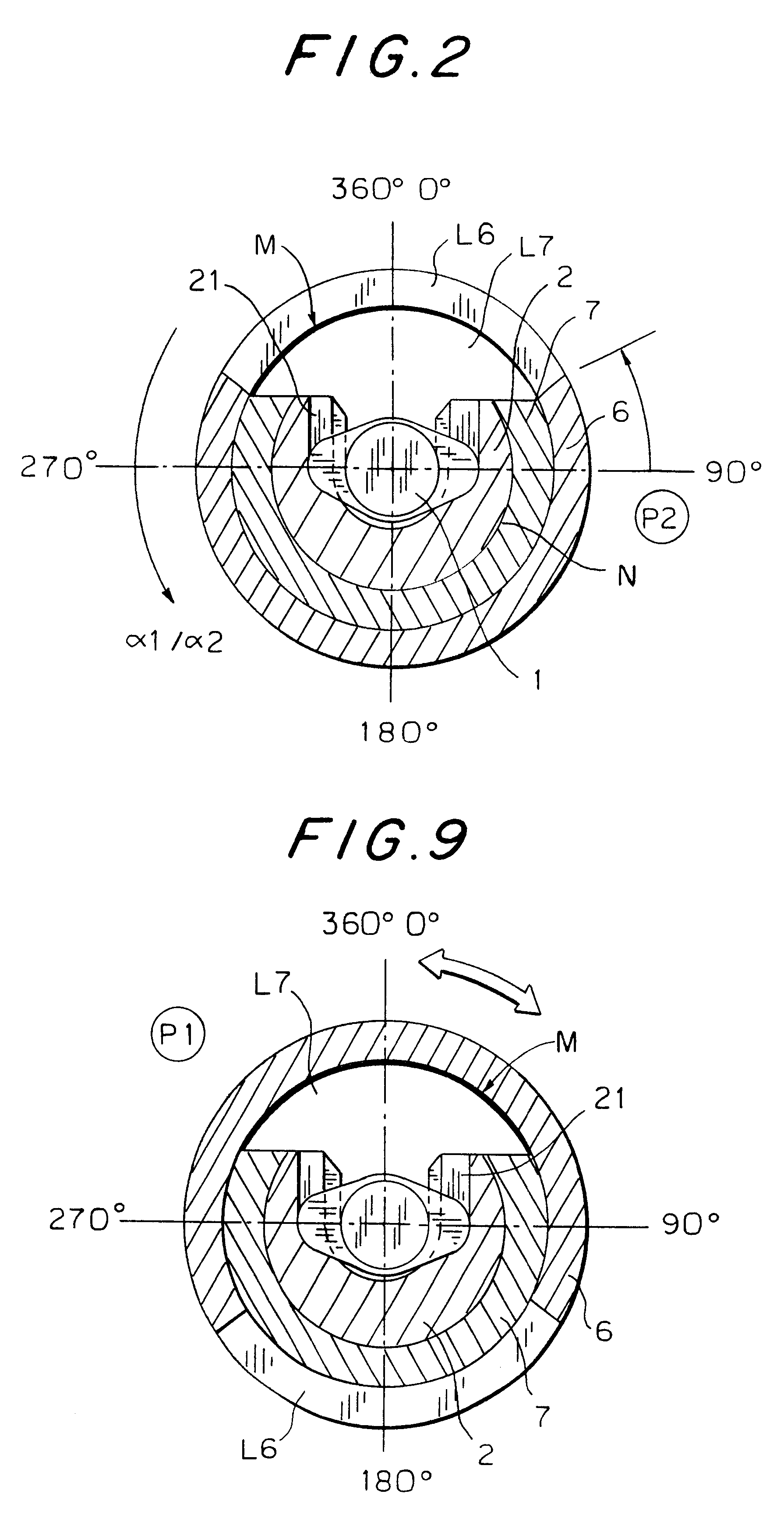
The housing 7 has, in its middle portion 7B adjoining the front portion 7C, a loading orifice L7 which extends over an acute circumferential angle with respect to the longitudinal axis F, in the exemplary embodiment illustrated,...


PUM


Abstract

An injection device that is used with a syringe, wherein the injection needle of the syringe is initially introduced into the skin and the injection fluid is injected afterwards. The injection device is essentially driven and controlled by a control sleeve (6) which can be displaced and/or rotated in relation to the housing (7) and which can be moved between a closing and functional position (P1) and an open and safety position (P2). In the closing and functional position, the control sleeve prevents access to the syringe and activates a release device for the injection process. In the open and safety position, a syringe (1) can be removed or inserted. A plurality of components carrying out the injection process (a slide (2) in which the syringe (1) is placed and a plunger (4) that impinges upon the syringe piston) are moved or controlled depending on the movement and position of the control sleeve or supported (for example, an ejection device for the syringe or a signaling device informing that injection has been completed). The device enables full-automatic injection that can be reliably carried out by patients themselves with few handling procedures.

Description

The present application is the national stage under 35 U.S.C. 371 of PCT / DE99 / 01244, filed Apr. 24, 1999.The invention relates to an injection device with a syringe, in particular a disposable syringe, for injecting an injection fluid under the skin.Carrying out medically appropriate injections by means of a syringe presupposes a minimum degree of medical knowledge and practical skill. Adherence to these requirements is usually guaranteed in the stationary hospital or care sector, since, here, syringes are handled by medically trained specialized personnel; however, with the increase in chronic illnesses due to the increasing life expectancy of the population, the domestic care sector is also increasing.The result of this is that the handling of syringes must increasingly be capable of being carried out by the medical lay public as patients for the purpose of self-treatment at home; apart from a certain threshold of inhibition when a syringe is applied, adherence to the above-mentio...

Claims


Application Information

Patent Timeline
Patent Type & Authority Patents(United States)
IPC IPC(8): A61M5/20A61M5/315A61M5/32
CPCA61M5/2033A61M5/31511A61M5/3157A61M2205/581A61M2005/2086A61M2005/3152A61M2005/206
Inventor WEBER
Owner BAYER INTELLECTUAL PROPERTY GMBH
Why Eureka
Try Eureka