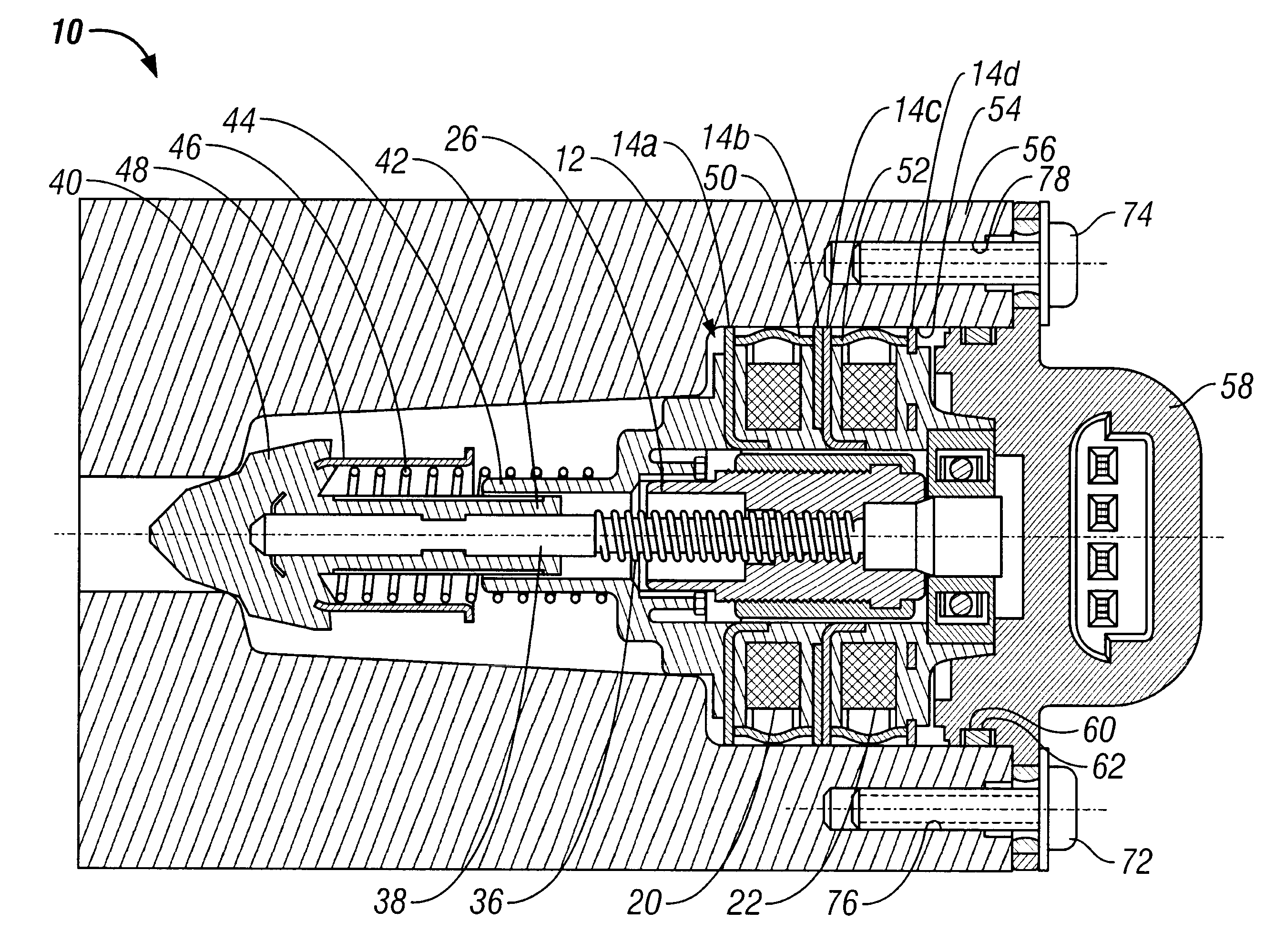
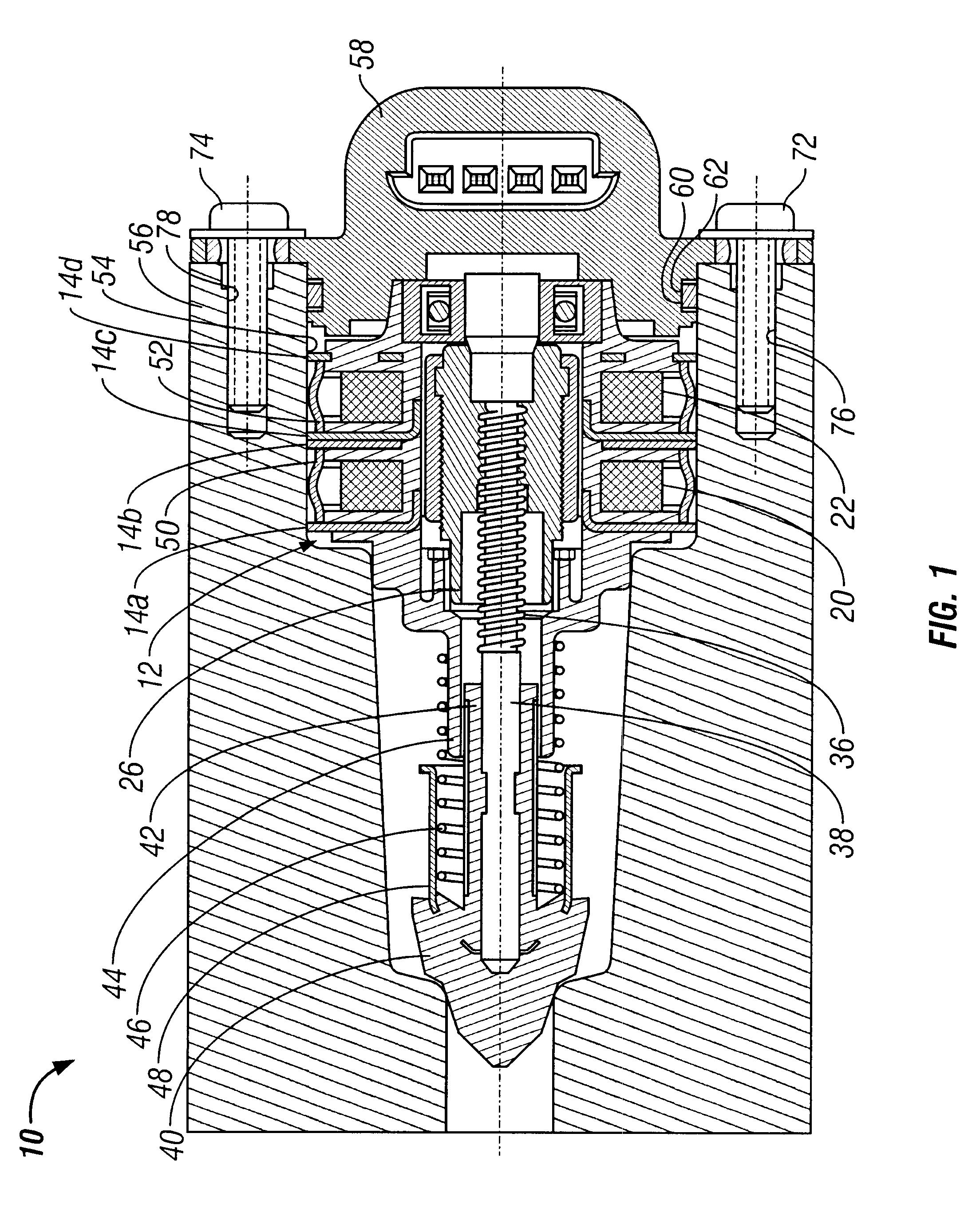
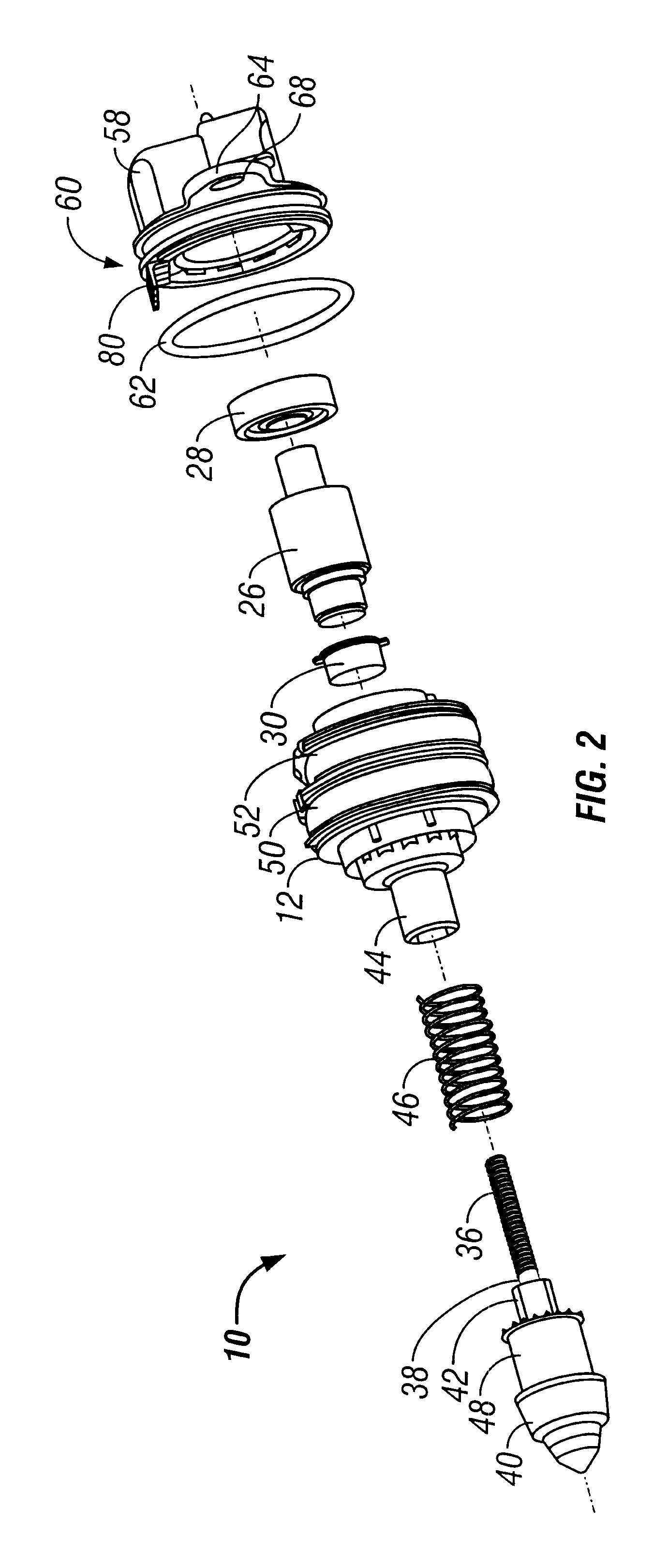
Magnetic device with flux return strip

a magnetic device and flux return technology, applied in the direction of windings, mechanical energy handling, magnetic circuit shapes/forms/construction, etc., can solve the problems of reducing the efficiency of the flux return path, affecting the performance of the motor, and affecting the ability to maintain consistent contact between the pole plate and the housing

Inactive Publication Date: 2002-09-24
MANNESMANN VDO AG
View PDF28 Cites 46 Cited by
  • Summary
  • Abstract
  • Description
  • Claims
  • Application Information

AI Technical Summary

Problems solved by technology

First, it is difficult to achieve consistent contact between the outer edges of the pole plates and the housing.
However, air gaps between the pole plates and housing decrease the efficiency of the flux return path and consequently, the performance of the motor.
Moreover, the ability to maintain consistent contact between the pole plates and housing is jeopardized in motors subjected to thermal cycling due to the expansion and contraction of the housing.
Second, a flux return path formed by a ferrous metal housing which encloses the entirety of a motor or by windings of magnetic wire around a motor's periphery often significantly adds to the mass of the motor.
Therefore, greater motor mass directly contributes undesirable added mass to the overall product.
Third, greater motor mass often has disadvantageous secondary effects.
In general, a heavier motor requires a mounting system of greater strength, and consequently of greater mass and potentially of greater complexity.
Thus, the additional mass of a ferrous metal housing also may indirectly contribute undesirable added mass and complexity to the overall product.
For motors that may have used discrete windings of magnetic material wire, such windings may contribute not only significant undesirable mass to the product, but also may require the added complexity of further winding operations.
Such additions result in undesirable added mass and complexity in the construction of the motor.

Method used


Image

  • Magnetic device with flux return strip
  • Magnetic device with flux return strip
  • Magnetic device with flux return strip

Examples


first embodiment

FIGS. 6 and 7 illustrate an alternative embodiment of a motor 110 employing advantages of the present invention. The internal componentry of motor 110 is common with that of motor 10 of the prior figures. Motor 110 differs from the motor 10 most notably in the structures related to housing and mounting the motor. Motor 110 has a conventional, flangeless plastic-bodied electrical connector 158. The connector 158 has a groove 160 that receives an O-ring seal 162 for sealing engagement with the interior wall of a protective motor housing 180. Using a magnetic flux return path that incorporates the aforementioned flux return strips and fixed pole plates permits the motor housing 180 of this embodiment preferably to be constructed of molded plastic, or alternatively of other suitable metallic or non-metallic materials. As noted above with respect to the first embodiment, the electrical connector and the housing can be of various shapes, configurations and constructions, and can accommoda...

second embodiment

In the second embodiment, as seen in FIGS. 6 and 7, the motor housing 180 has a landing 182 against which an O-ring seal 184 rests for sealing engagement with a bore 154 of manifold 156. As with the sealed engagement between the electrical connector and the bore of the mating component in the first exemplary embodiment, the housing, the mating component and the seal therebetween may be of various shapes, configurations and constructions to provide sealing engagement between a surface of the housing and a surface of the mating component. In the second exemplary embodiment, housing 180 also has a second landing 186 that receives a retainer 188 for retaining engagement with a second bore 190 of manifold 156. The retainer 188 has inward facing spring tabs 192 that make it self-retaining when pressed onto the landing 186 of housing 180. The retainer 188 installed on motor housing 180 also has outward facing spring tabs 194 that make it self-retaining when the motor housing 180 is pressed...


PUM


Abstract

A magnetic device having a stator assembly having a magnetic flux return path comprising at least a pair of pole plates located a fixed distance apart from each other and at least one flux return strip pressed between each pair of spaced apart pole plates, and a rotor assembly having permanent magnetic material and being disposed for rotation relative to the stator assembly. Use of the flux return strip eliminates the need for a housing of ferrous material to complete the flux return path and facilitates flexible design of light-weight non-metallic housings and mounting systems or integral mounting to mating components.

Description

1. Field of the InventionThe present invention generally relates to devices employing magnetic flux return paths such as electric motors. More particularly, the invention relates to magnetic devices having at least one flux return strip pressed between pole plates to complete a magnetic flux path or circuit. In another aspect of the invention, use of the flux return strips eliminates the need for a metal housing of ferrous material to complete the flux return path. This facilitates flexible design of light-weight mounting systems or integral mounting of the magnetic devices to mating components in product assemblies.2. Discussion of the Prior ArtMagnetic devices of varying designs, such as the many forms of electric motors, are well known and frequently used for linear or rotating actuation in a myriad of products. The motors commonly use a magnetic flux return path about their periphery that incorporates ferrous material.Many motors, such as the design shown in U.S. Pat. No. 5,567,...

Claims


Application Information

Patent Timeline
Patent Type & Authority Patents(United States)
IPC IPC(8): H02K1/14H02K7/14H02K5/22H02K7/06H02K5/10
CPCH02K1/145H02K5/225H02K7/14H02K5/10H02K7/06
Inventor INESON, DAVID J.LOXSOM, WILLIAMCHRISTIAENS, ALOIS
Owner MANNESMANN VDO AG
Why Eureka
Try Eureka