Antenna device and portable wireless communication apparatus

a wireless communication and antenna device technology, applied in the direction of antennas, antenna details, antenna earthings, etc., can solve the problem that single radio communication systems tend to be incapable of providing a sufficient number of circuits

Inactive Publication Date: 2002-09-24
SONY CORP
View PDF2 Cites 20 Cited by
  • Summary
  • Abstract
  • Description
  • Claims
  • Application Information

AI Technical Summary

Benefits of technology

Since the input impedance at the open ends of the conductive planar plates can be brought close to infinity at the plurality of radio communication frequencies respectively, it is possible to limit radiation of electromagnetic waves by restricting the high-frequency currents supplied to the above described conductive planar plates and grounding conductors, thereby securely reducing an amount of electromagnetic waves to be absorbed by a human body in correspondence to at least two or more radio communication systems which use different radio communication frequencies even when any radio communication frequency is used.

Problems solved by technology

As portable wireless communication apparatuses have rapidly prevailed in recent years, only a single radio communication system tends to be incapable of providing a sufficient number of circuits.

Method used


Image

  • Antenna device and portable wireless communication apparatus
  • Antenna device and portable wireless communication apparatus
  • Antenna device and portable wireless communication apparatus

Examples


first embodiment

(1) First Embodiment

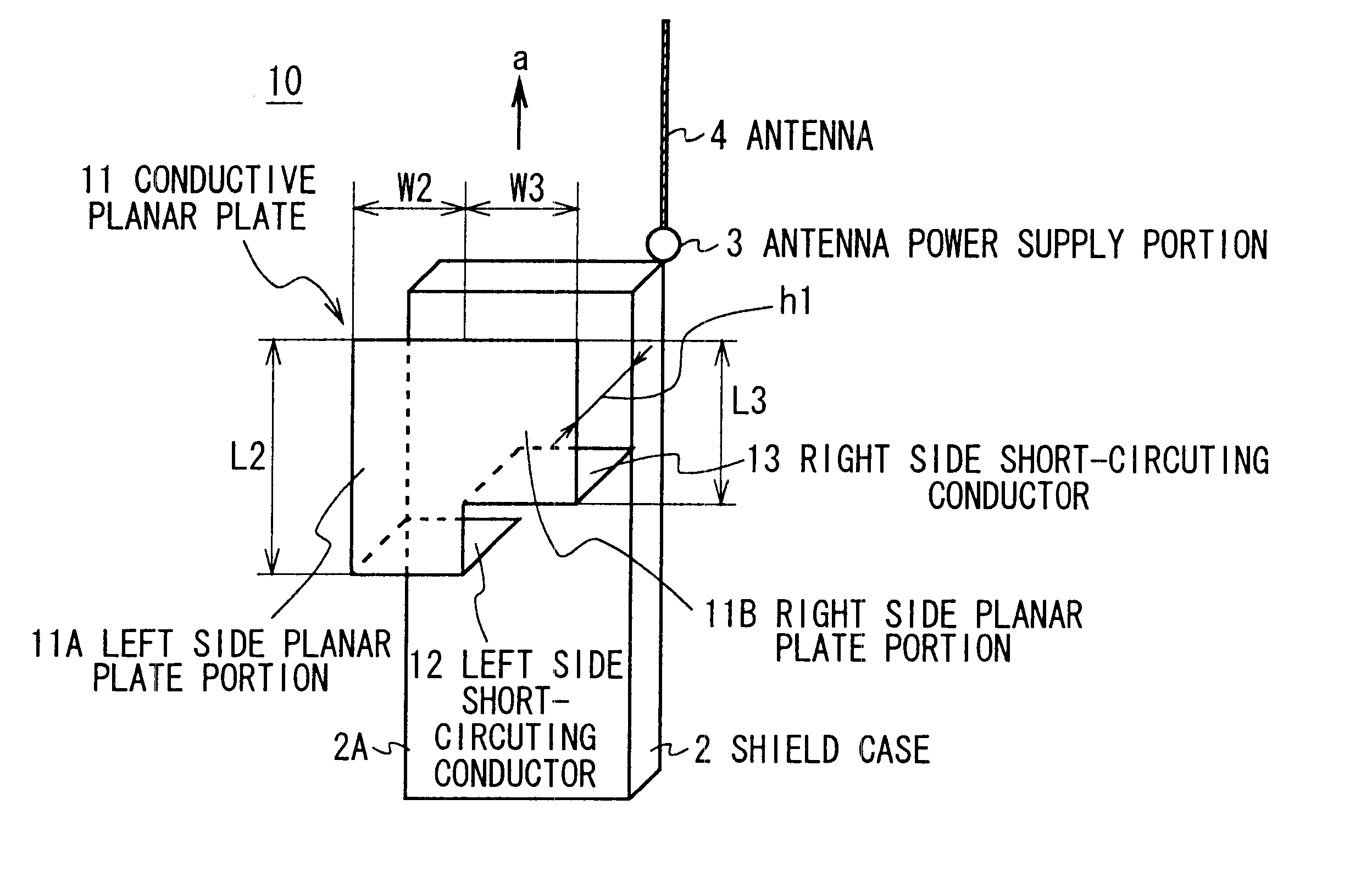
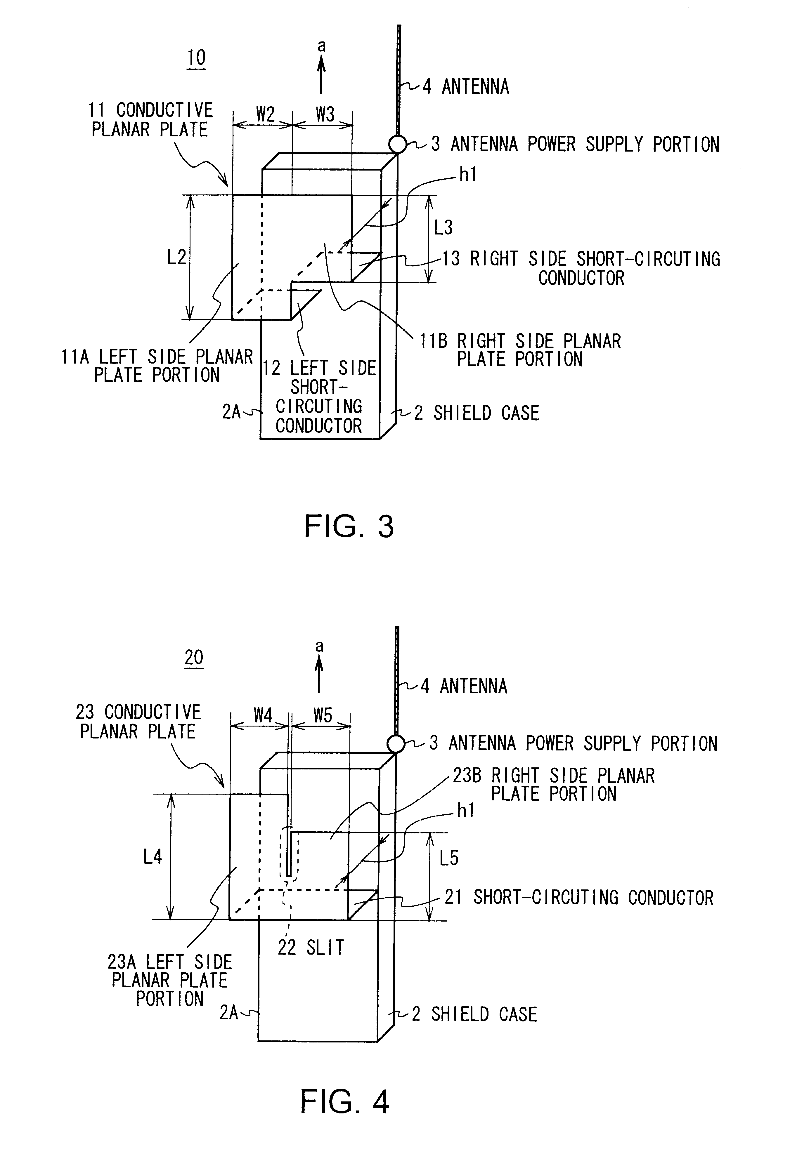
In FIG. 3 in which members corresponding to those shown in FIG. 1 are denoted by the same reference numerals, reference numeral 10 denotes a portable wireless communication apparatus as a whole according to a first embodiment of the present invention. A circuit substrate (not shown) required for carrying out radio communication is accommodated in a cabinet (not shown) made of a non-conductive material and covered with a shield case 2 used as a ground member.

Since the internally accommodated circuit substrate is covered with the shield case 2, the portable wireless communication apparatus 10 is configured so that a transmitting-receiving circuit and other various kinds of circuits mounted on the circuit substrate do not produce adverse influences on each other, an antenna 4 and other appliances.

Furthermore, the internal circuit substrate is configured to generate a transmission signal of a predetermined signal format with the transmitting-receiving circuit for com...

second embodiment

(2) Second Embodiment

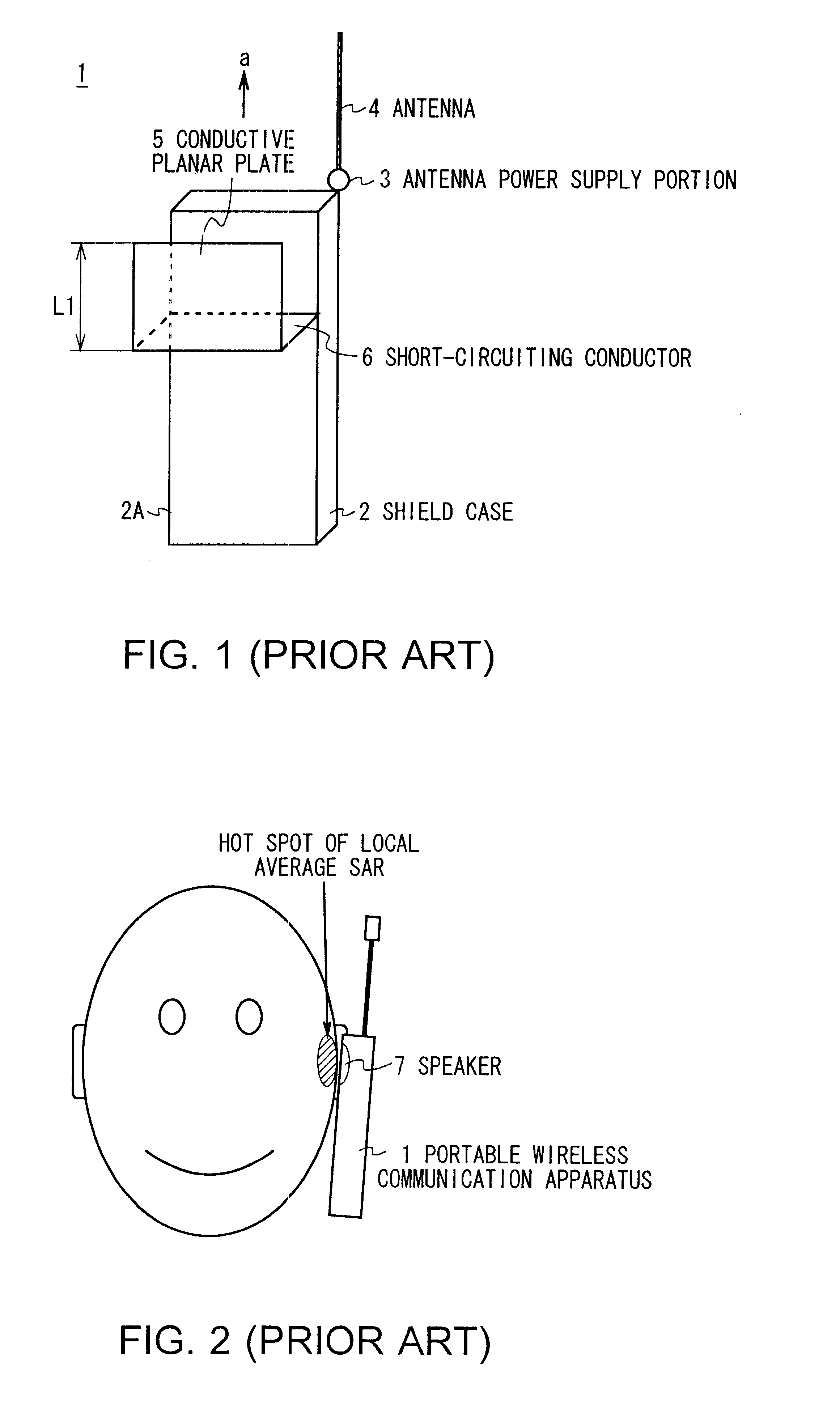
In FIG. 4 in which members corresponding to those shown in FIG. 3 are denoted by the same reference numerals, reference numeral 20 denotes a portable wireless communication apparatus as a whole according to a second embodiment of the present invention. Description will be made below also on an assumption that the hot spot at which the local average SAR has a maximum value is located in the vicinity of an ear which is to be brought into contact with a speaker (not shown).

The portable wireless communication apparatus 20 uses a conductive planar plate 23 disposed at a location which is nearly in parallel with a top surface 2A of a shield case 2 and at a height h1 as measured from the above described top surface 2A, and the above described conductive planar plate 23 is short-circuited to the shield case 2 by a shoring conductor 21.

The conductive planar plate 23 is configured as a single plate consisting of a rectangular left side planar plate portion 23A having a di...


PUM


Abstract

An antenna device and a portable wireless communication apparatus lower a local average specific absorption rate (SAR) in correspondence to at least two or more kinds of radio communication systems using different radio communication frequencies even when any radio communication frequency is used. Input impedance at open ends of conductive planar plates are brought close to infinity at first and second radio communication frequencies and restrict emission of electromagnetic waves by restricting a high-frequency current to be supplied to the above described conductive plates and a shield case, thereby securely lowering the local average SAR in correspondence to at least two or more kinds of radio communication systems using different radio communication frequencies even when any radio communication frequency is used.

Description

1. Field of the InventionThe present invention relates to an antenna device and a portable wireless communication apparatus, and more particularly, is suitably applicable, for example, to a portable wireless communication apparatus which is configured to correspond to at least two kinds of radio communication systems using different radio communication frequencies.2. Description of the Related ArtAs portable wireless communication apparatuses have rapidly prevailed in recent years, only a single radio communication system tends to be incapable of providing a sufficient number of circuits. It is therefore conceived to reserve a necessary number of circuits by using another radio communication system which uses a different frequency bands and, owing to remarkable progresses made in a technology for compact and light-weight configurations, there has been developed a terminal which allows a single portable wireless communication apparatus to use two kinds of radio communication systems....

Claims


Application Information

Patent Timeline
Patent Type & Authority Patents(United States)
IPC IPC(8): H01Q1/24H01Q1/52H01Q5/00H01Q1/00H01Q5/10H04B1/38
CPCH01Q1/245H01Q5/28H01Q1/526H01Q1/48
Inventor ITO, HIROKI
Owner SONY CORP
Why Eureka
Try Eureka