Current detector

a current detector and detector technology, applied in the direction of instruments, magnetic measurements, measurement using dc-ac conversion, etc., can solve the problems of increased cost of current detector, inability to enhance current detection precision, and inability to precisely detect current flowing through the to-be-measured conductor

Inactive Publication Date: 2002-10-01
YAZAKI CORP
View PDF3 Cites 60 Cited by
  • Summary
  • Abstract
  • Description
  • Claims
  • Application Information

AI Technical Summary

Problems solved by technology

H5-223849, the magnetic flux generated by a current flowing through a conductor other than the to-be measured conductor becomes disturbance which affects the detection result and thus, there is a problem that a current flowing through the to-be measured conductor can not be detected precisely.
Especially when a current is detected using a magnetic-electric power converting element in an environment in which a plurality of conductors are arranged side-by-side

Method used


Image

  • Current detector
  • Current detector
  • Current detector

Examples


first embodiment

(First Embodiment)

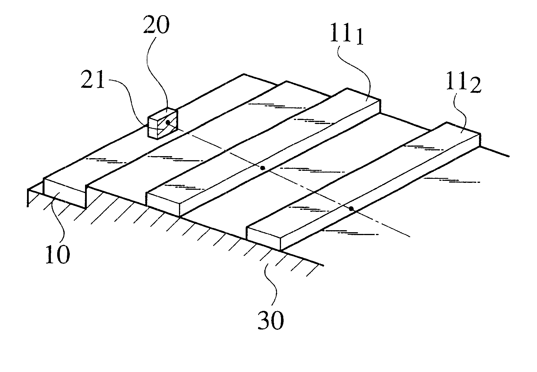
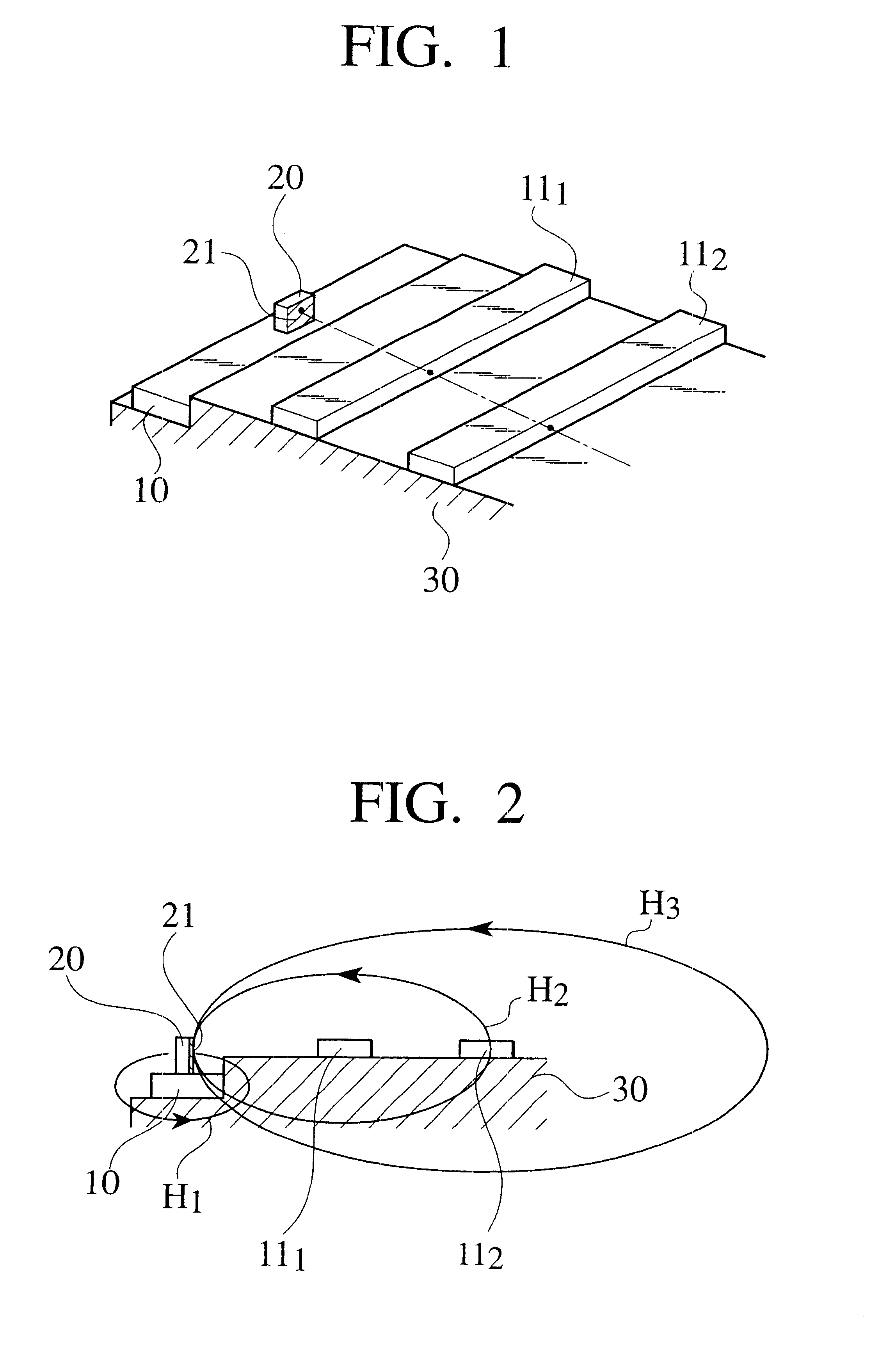
FIG. 1 is a perspective view showing a structure of a current detector according to a first embodiment of the present invention. This current detector comprises a conductor to be measured (which will be referred to as "to-be measured conductor, hereinafter) 10, a first conductor 11.sub.1, a second conductor 11.sub.2, a Hall element 20 and a substrate 30. These elements are usually accommodated in an electric connection box (not shown). In the first embodiment, a magnetic-force collecting core is not used.

The to-be measured conductor 10 is a linear conductor through which a to-be measured current flows, and the Hall element 20 is secured on the to-be measured conductor 10. The Hall element 20 corresponds to a magnetic-electric power converting element of the present invention. The Hall element 20 generates a voltage (Hall voltage) signal corresponding to a magnetic flux density entering a magnetic-force sensing face (magnetic flux detecting face) of the Hall element...

second embodiment

(Second Embodiment)

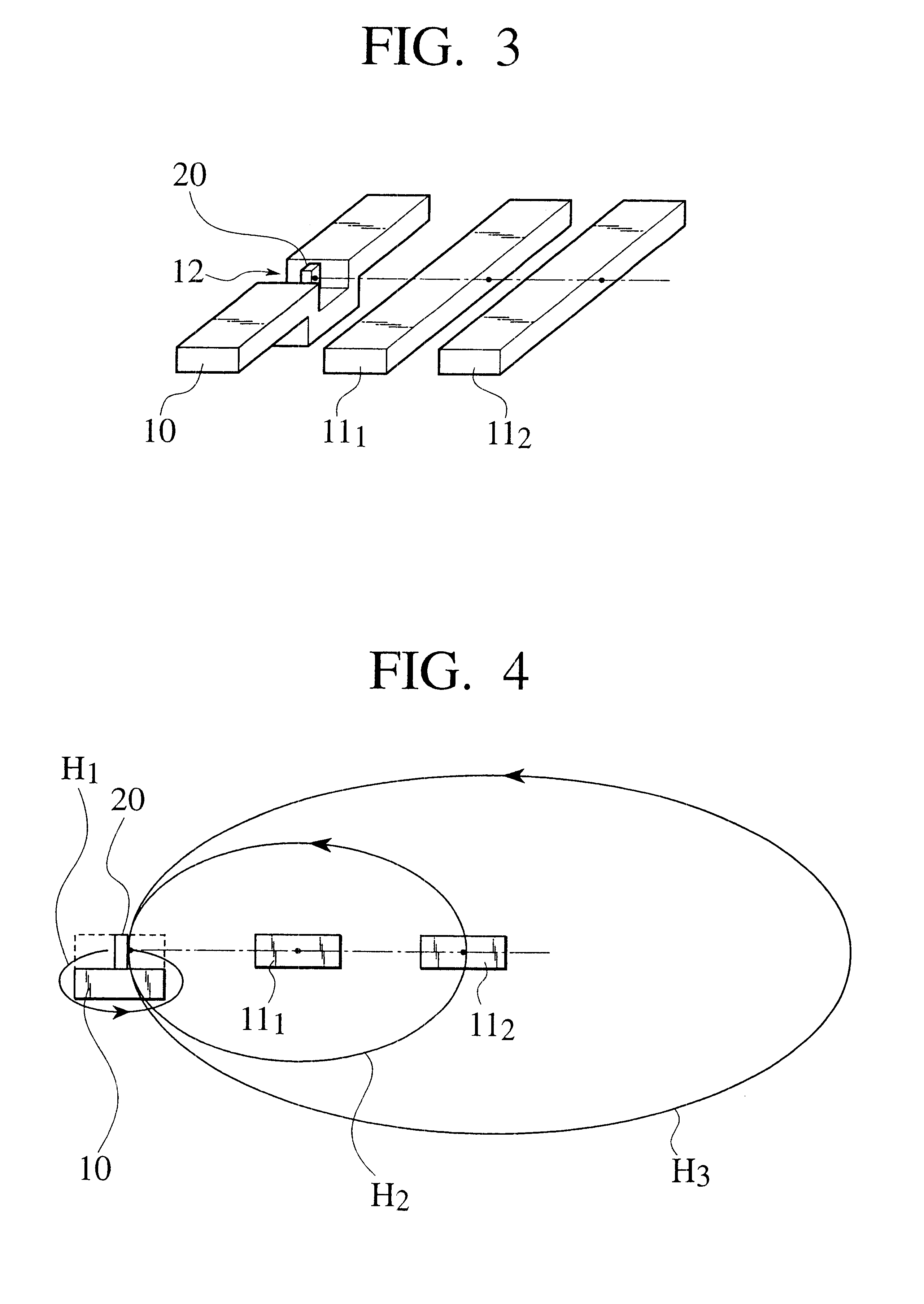
FIG. 3 is a perspective view showing a structure of a current detector according to a second embodiment of the invention. This current detector comprises a conductor to be measured 10, a first conductor 11.sub.1, a second conductor 11.sub.2, a Hall element 20 and a substrate 30. These elements are usually accommodated in an electric connection box (not shown). In the second embodiment, a magnetic-force collecting core is not used.

The to-be measured conductor 10 is a conductor through which a to-be measured current flows. The to-be measured conductor 10 is formed with a bent portion 12 formed by bending a portion of the to-be measured conductor 10 into a U-shape. The Hall element 20 is secured to the bent portion 12. The Hall element 20 corresponds to a magnetic-electric power converting element of the present invention, and is the same as that used in the first embodiment.

The first conductor 11.sub.1 and the second conductor 11.sub.2 are linear conductors through ...

third embodiment

(Third Embodiment)

A current detector of the third embodiment is different from those of the first and second embodiments in that a plurality of to-be conductors are provided.

FIG. 6 is a perspective view showing a structure of the current detectors according to a third embodiment of the invention, FIG. 7 is a plan view of the conductors, and FIG. 8 is a side view of the conductors. This current detector comprises a first to-be measured conductor 10.sub.1, a second to-be measured conductor 10.sub.2, a third to-be measured conductor 10.sub.3, a first Hall element 20.sub.1, a second Hall element 20.sub.2 and a third Hall element 20.sub.3. These elements are usually accommodated in an electric connection box (not shown). In the third embodiment, a magnetic-force collecting core is not used.

The first to third to-be measured conductors 10.sub.1 to 10.sub.3 are conductors through which to-be measured currents flow, and have the same structures as that of the to-be measured conductor 10 of t...


PUM


Abstract

A current detector having a linear conductor 111, 112, a linear to-be measured conductor 10 disposed substantially in parallel to the conductor 111, 112 and through which a to-be measured current flows. A Hall element 20 disposed in the vicinity of the to-be measured conductor 10 such that a magnetic flux generated by the to-be measured current flowing through the to-be measured conductor 10 enter into a magnetic-force sensing face 21 substantially perpendicularly. A substrate 30 for supporting the conductor and the to-be measured conductor 10 such that the magnetic flux generated by a current flowing through the conductor becomes substantially parallel to the magnetic-force sensing face +21 in the magnetic-force sensing face 21 of the Hall element 20.

Description

1. Field of the InventionThe present invention relates to a current detector for detecting a current flowing through an electric circuit mounted to equipment such as an automobile, and more particularly, to a technique for enhancing a detection precision of a current when a plurality of conductors are arranged side-by-side.2. Description of Related ArtThere is a conventionally known current detector for detecting a current flowing through an electric circuit mounted in, e.g., an automobile using a Hall element which is one of magnetic-electric power converting element. One example of such current detectors is disclosed in Japanese Patent Application Laid-open No. H5-223849. This current detector comprises a conductor flowing a current to be detected (which will be referred to as "to-be detected current", hereinafter), and having a notch formed on the same plane, or having a loop-like current path formed by bending. The current detector also comprises a magnetic-electric power conver...

Claims


Application Information

Patent Timeline
IPC IPC(8): G01R15/14G01R15/20G01R19/00
CPCG01R15/202
Inventor TAMAI, YASUHIROIKUTA, YOSHINORIGOHARA, TAKASHIMORIMOTO, MITSUAKI
Owner YAZAKI CORP
Why Eureka
Try Eureka