Toe web cutter with stationary blade unit

a technology of stationary blades and cutters, which is applied in the field of cutters, can solve the problems of loss of correct alignment, difficult to achieve the correct alignment, and the blade positioned against the carcass begins to move,

Inactive Publication Date: 2002-10-08
JARVIS PROD
View PDF24 Cites 5 Cited by
  • Summary
  • Abstract
  • Description
  • Claims
  • Application Information

AI Technical Summary

Benefits of technology

A drive mechanism is connected to the tool body and drives one of the blade units relative to the other blade unit. The driven blade unit pivots and the other blade unit is stationary, defining a toe web cutting location at a fixed position relative to the stationary blade unit and the tool body. This allows the tool to be guided into correct alignment with the toe web by aligning the stationary blade unit relative to the toe web.

Problems solved by technology

Achieving this correct alignment, however, has been difficult when using existing toe web cutters.
The difficulty resides in the fact that both blades move relative to the cut point located at a position that is midway between them.
However, when the tool is actuated, the blade positioned against the carcass begins to move and correct alignment is lost.
The tool is relatively heavy, however, and repeatedly moving it in a counteracting motion is tiring.
However, achieving the correct alignment this way is also difficult as there is no part of the tool actually located at the cut point that can be used to contact the carcass and hold the tool at the right position.
Even when correct alignment is initially achieved, because both blade units move during the cut, and because neither is in contact with the carcass, correct alignment can be lost before the cut actually begins.
Using either method, cutting is awkward due to the relative motion between the cut point and both of the blade units.

Method used


Image

  • Toe web cutter with stationary blade unit
  • Toe web cutter with stationary blade unit
  • Toe web cutter with stationary blade unit

Examples


Embodiment Construction

)

In describing the preferred embodiment of the present invention, reference will be made herein to FIGS. 1-4 of the drawings in which like numerals refer to like features of the invention.

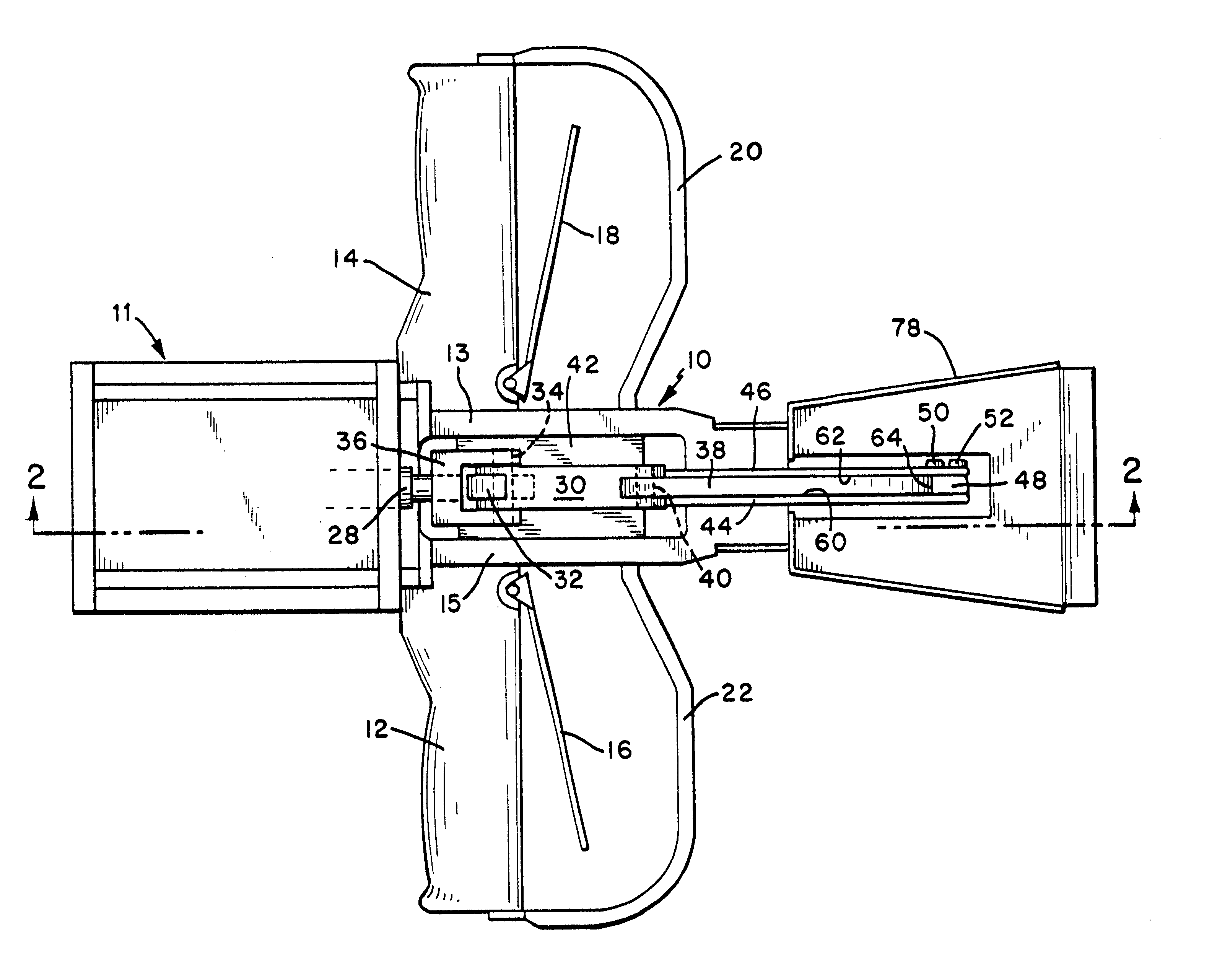
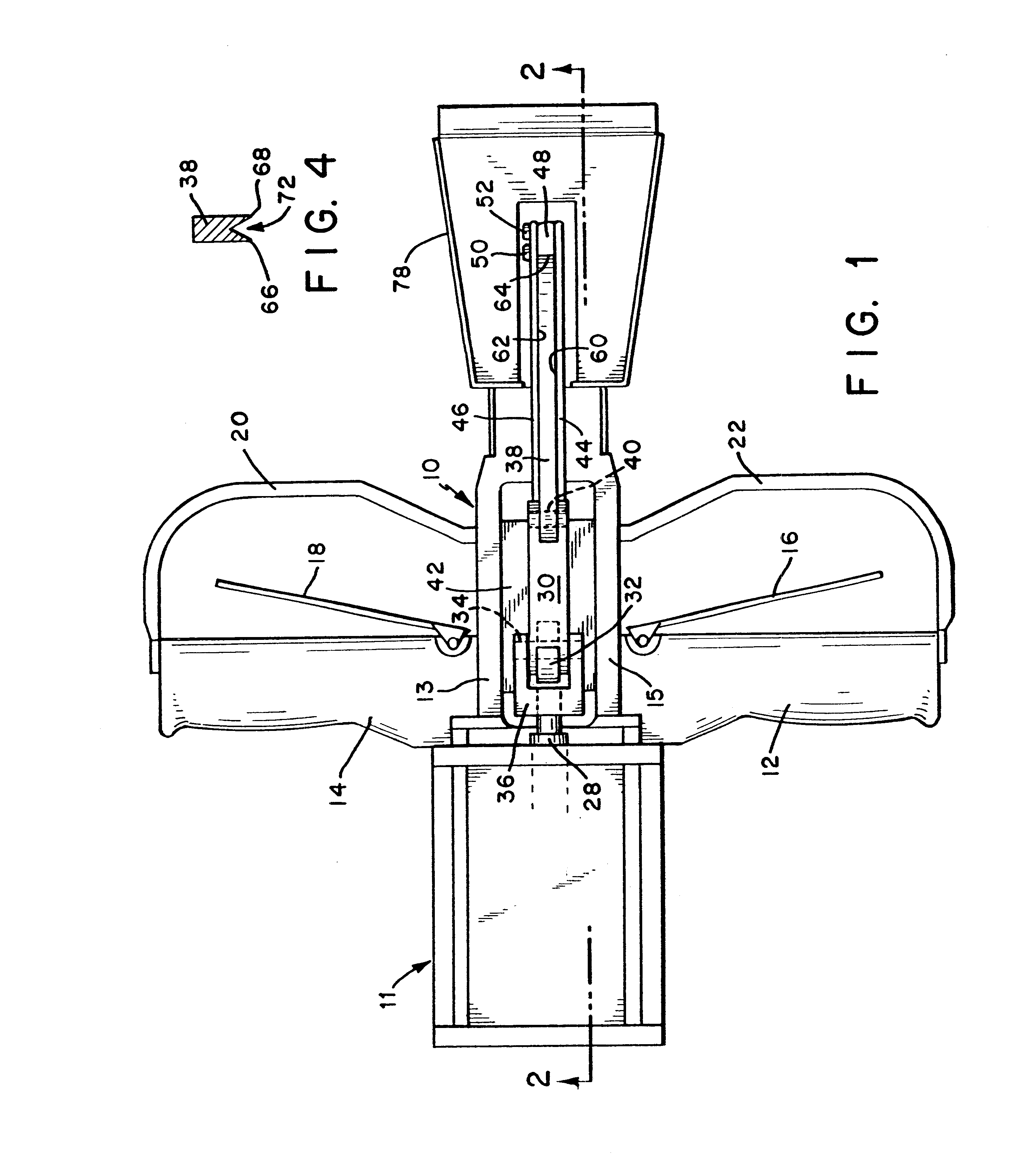
Referring to FIG. 1 of the present invention, the toe web cutter includes a tool body 10 having a right handle 12 and a left handle 14. Corresponding triggers 16, 18 are mounted on the handles so that the operator's hands can actuate them while the tool is being held. The triggers operate a pneumatic drive mechanism 11 mounted on the body (see FIGS. 2 and 3). The drive mechanism may be mounted inside the body, or as-shown, mounted to the exterior of the body.

For safety, both the right trigger 16 and the left trigger 18 must be operated in order for the blades to close. This ensures that the operator's hands will be on the handles and out of the cutting area. Handle guards 20 and 22 are provided to further protect the operator's hands during tool use.

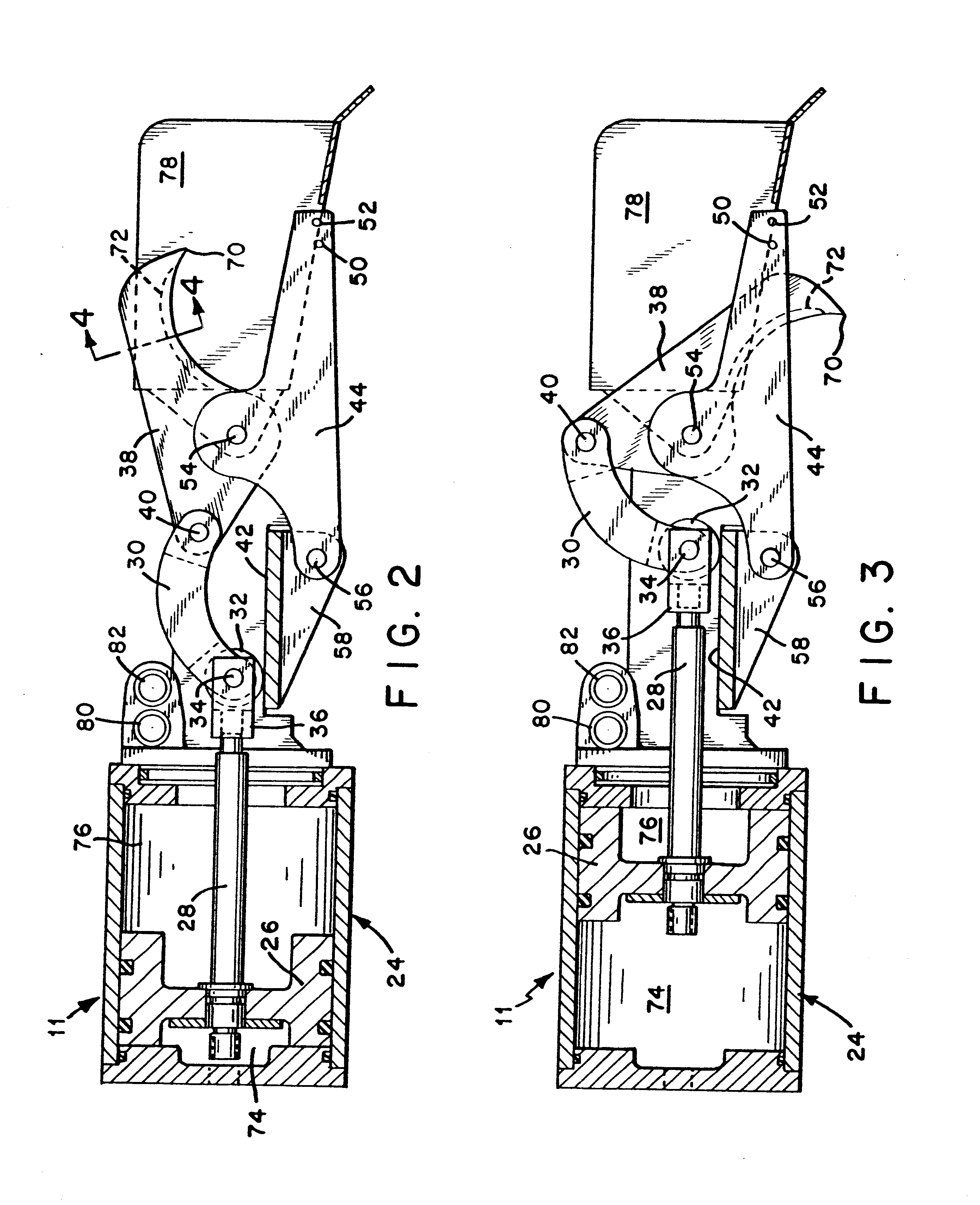
Referring to FIG. 2, the drive mechanism 11 compr...


PUM


Abstract

A toe web cutter has a pivoted inner hooked blade and stationary outer blades adjacent to the sides and end of the inner blade. Cutting edges on the adjacent blades produce an elongated cut to remove the web from between the toes of a carcass. The stationary outer blades allow the tool to be aligned before the cut is made by placing the stationary blades in contact with the web at the desired location for the cut. The inner blade is pivoted by a trigger-operated pneumatic drive mechanism, which includes a piston and a drive rod. The drive rod is connected through a link to drive the inner blade. The link produces a side load on the drive rod that is counteracted by a wheel mounted on the end of the drive rod and by a fixed reaction plate that supports the wheel as it rolls.

Description

1. Field of the InventionThe present invention relates to cutters used in the meat processing industry to remove the web from between the toes of a carcass.2. Description of Related ArtToe web cutters are used in meat processing facilities to remove the web from between the toes of a carcass, such as a hog carcass.In toe web cutters of the type shown in U.S. Pat. No. 5,454,754, an inner hook-shaped blade is pivotally connected between an outer pair of side blades. An end blade mounted between two parallel side blades forms an outer blade unit that surrounds three sides of the inner blade. The outer blades and the inner hooked blade define a cut that removes the toe web as the inner blade passes between the side outer blades and past the end blade. A drive mechanism simultaneously pivots both the outer blade unit and the inner hooked blade to make the cut.The tip of the inner blade passes by the end blade and defines a cut point. The cut point is at the maximum depth to which the web...

Claims


Application Information

Patent Timeline
Patent Type & Authority Patents(United States)
IPC IPC(8): A22B5/00
CPCA22B5/0058
Inventor GWYTHER, PETER
Owner JARVIS PROD
Why Eureka
Try Eureka