Switching power supply
a technology of switching power supply and power supply, which is applied in the direction of electric variable regulation, process and machine control, instruments, etc., can solve the problems of reducing affecting the efficiency of the switch, and causing a normal loss relative to large,
- Summary
- Abstract
- Description
- Claims
- Application Information
AI Technical Summary
Problems solved by technology
Method used
Image

Examples
first embodiment
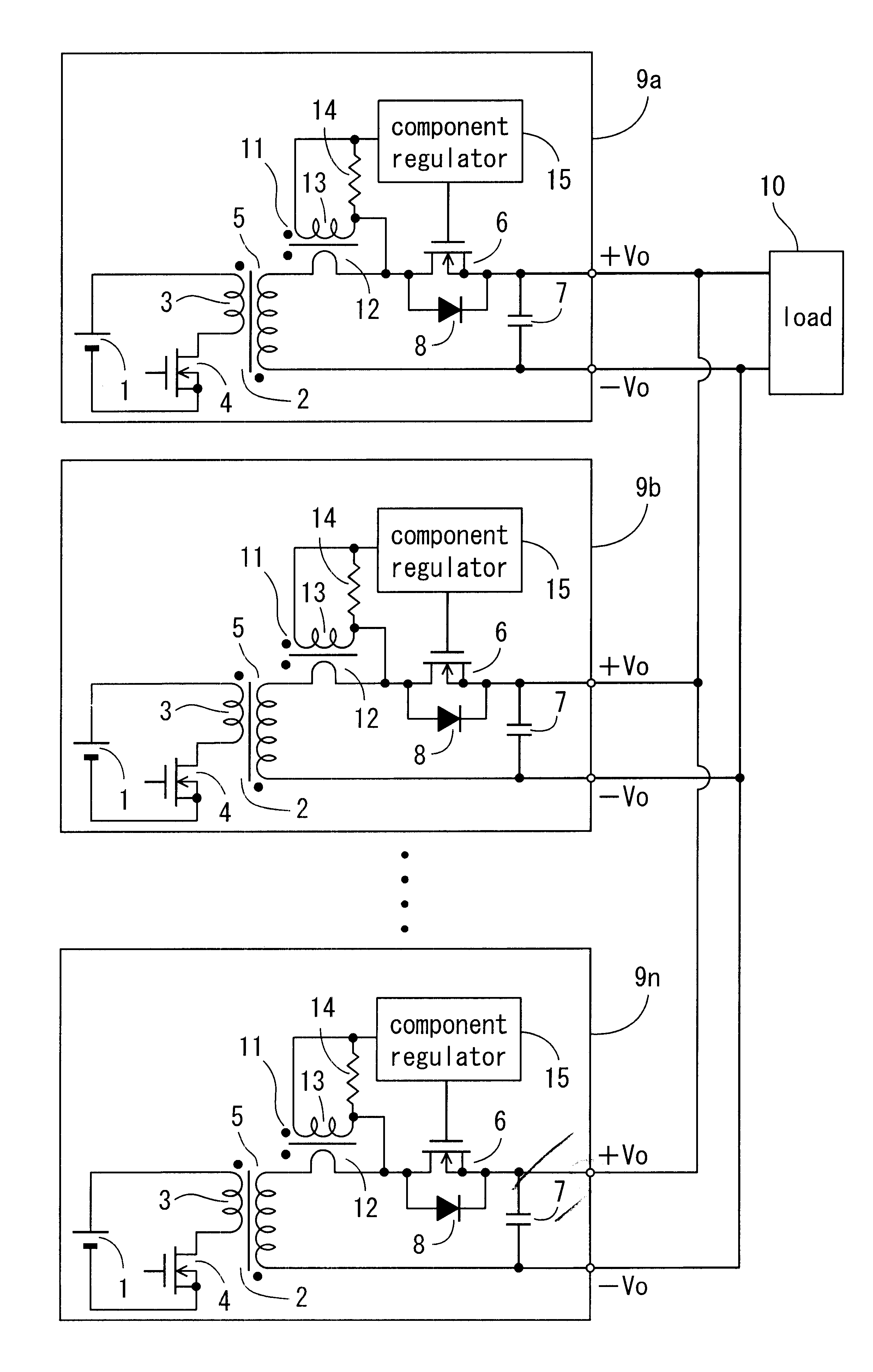
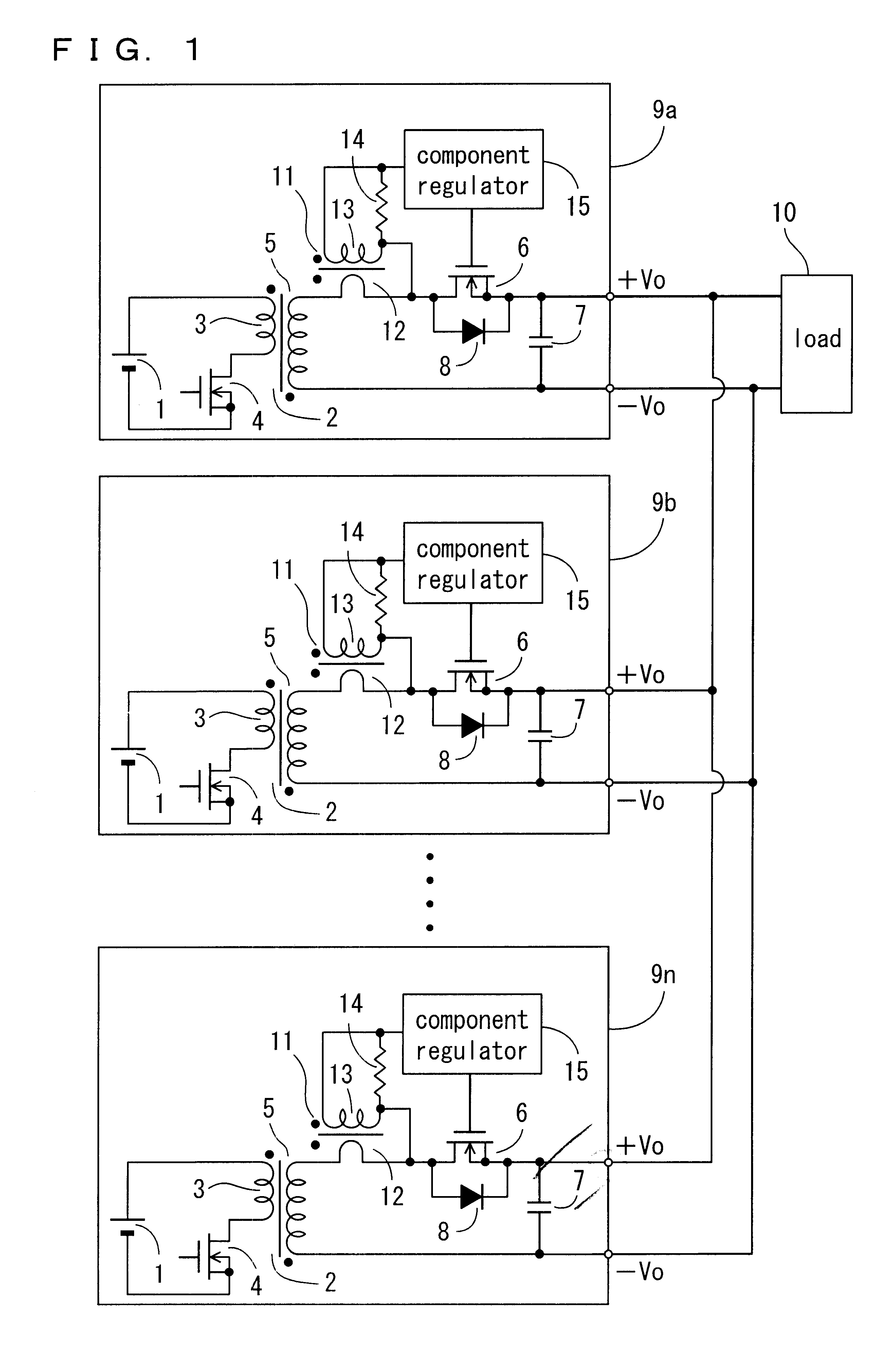
FIG. 1 to FIG. 3 are schematics showing the present invention. In FIG. 1 showing an entire topology of a regulator of the invention, reference numeral 1 denotes a direct current source for feeding DC input voltage, while reference numeral 2 denotes a main transformer in which a primary side is isolated from a secondary side. A series circuit of a primary winding 3 of the transformer 2 and a main switching element 4 such as MOS FET, for example, is connected across both terminals of the direct current source 1. A rectifying switching element 6 such as MOS FET, for example, is connected to a secondary winding 5 of the transformer 2, said element 6 serving as a rectifier element forming a synchronous rectifier circuit. Further, a rectifier smoothing circuit in the secondary of the transformer 2 is constructed by this rectifying switching element 6 and a smoothing capacitor 7. In the meantime, reference numeral 8 denotes a body diode built in the rectifying switching element 6, while +V...
third embodiment
A fourth embodiment of the present invention is shown in FIG. 7 and FIG. 8 and is described using the same reference symbols for the same parts as described in the foregoing embodiments. In the schematic in FIG. 7 showing this embodiment, in place of the resistor 14 in said turn-off circuit 16 is provided a differential circuit 63 comprising a capacitor 61 and a resistor 62, which differentiates a detection signal induced in the secondary winding 13 of the current transformer 11, said differential circuit 63 being connected across the secondary winding 13 of the current transformer 11. Likewise, the topology of the other parts than those described above is the same as the foregoing
In the first to the third embodiments, whilst the voltage across the resistor 14 becomes a waveform as shown by broken lines in FIG. 8, positive and negative trigger signals are generated across the resistor 62, corresponding to the building-up and building-down of the current generated in the secondary wi...
fifth embodiment
the present invention is shown in FIG. 9 and is described using the same reference symbols for the same parts as those described in the above-mentioned embodiment. The fifth embodiment shows an example where the structure of the invention is applied to a switching regulator comprising a forward type DC / DC converter. More specifically, said rectifying switching element 6 is connected, as a rectifier element to be connected to the secondary winding 5 of the transformer 2, instead of a conventional flywheel diode, while the same drive circuit 17 and the same turn-off circuit 16 as those described in the first embodiment are provided. Of course, the circuit topologies in the second to the fourth embodiment may be provided instead of these circuits.
The primary winding 2 and secondary winding 5 of the transformer 1 are connected with additive polarity unlike in a flyback type. Another rectifying switching element 52, composing a synchronous rectifier circuit together with the rectifying s...
PUM
 Abstract
Description
Claims
Application Information
 - Generate Ideas
- Intellectual Property
- Life Sciences
- Materials
- Tech Scout
- Unparalleled Data Quality
- Higher Quality Content
- 60% Fewer Hallucinations
Browse by: Latest US Patents, China's latest patents, Technical Efficacy Thesaurus, Application Domain, Technology Topic, Popular Technical Reports.
© 2025 PatSnap. All rights reserved.Legal|Privacy policy|Modern Slavery Act Transparency Statement|Sitemap|About US| Contact US: help@patsnap.com