
Tool for aligning vehicle fender on vehicle during assembly

Inactive Publication Date: 2002-10-15
PASLIN COMPANY THE
View PDF36 Cites 23 Cited by
  • Summary
  • Abstract
  • Description
  • Claims
  • Application Information

AI Technical Summary

Benefits of technology

More particularly, it is an object of the present invention to provide a method and apparatus for aligning a component with respect to an adjacent component which relies on a minimum of human labor.
Yet an additional object of the present invention is to provide such a method and apparatus which incorporates a spacing wedge fitted to the frame for consistently and accurately spacing adjacent components.

Problems solved by technology

In the assembly of an automotive vehicle, body components are often difficult to correctly attach to the vehicle.
The reason for such difficulty is generally founded in the fact that automobile components such as fenders, trunk lids, engine hoods, and roofs tend to be bulky and difficult to attach.
In part due to their bulk, these components are generally difficult to align on the vehicle in that their sheer size often leads to their flexing during the assembly operation.
The result of such flexing unfortunately results in a poorly fitted fender.
Presently, the assembly of body components onto the vehicle frame is an arduous and demanding task that is largely done by highly skilled artisans.
While generally providing some level of accuracy, known methods of attaching methods fail in large part due to variations in the "principal locating points".
Accordingly, because of such variations in "principal locating points", present methods of attaching components during the production of an automotive vehicle are inadequate.
In addition, beyond unsatisfactory attachment results, the present method of employing two workers to install each component is very labor intensive and subject to cost and reliability problems commonly associated with such assembly techniques.

Method used


Image

  • Tool for aligning vehicle fender on vehicle during assembly
  • Tool for aligning vehicle fender on vehicle during assembly
  • Tool for aligning vehicle fender on vehicle during assembly

Examples


Embodiment Construction

The drawings disclose the preferred embodiments of the present invention. While the configurations according to the illustrated embodiments are preferred, it is envisioned that alternate configurations of the present invention may be adopted without deviating from the invention as portrayed. The preferred embodiments are discussed hereafter.

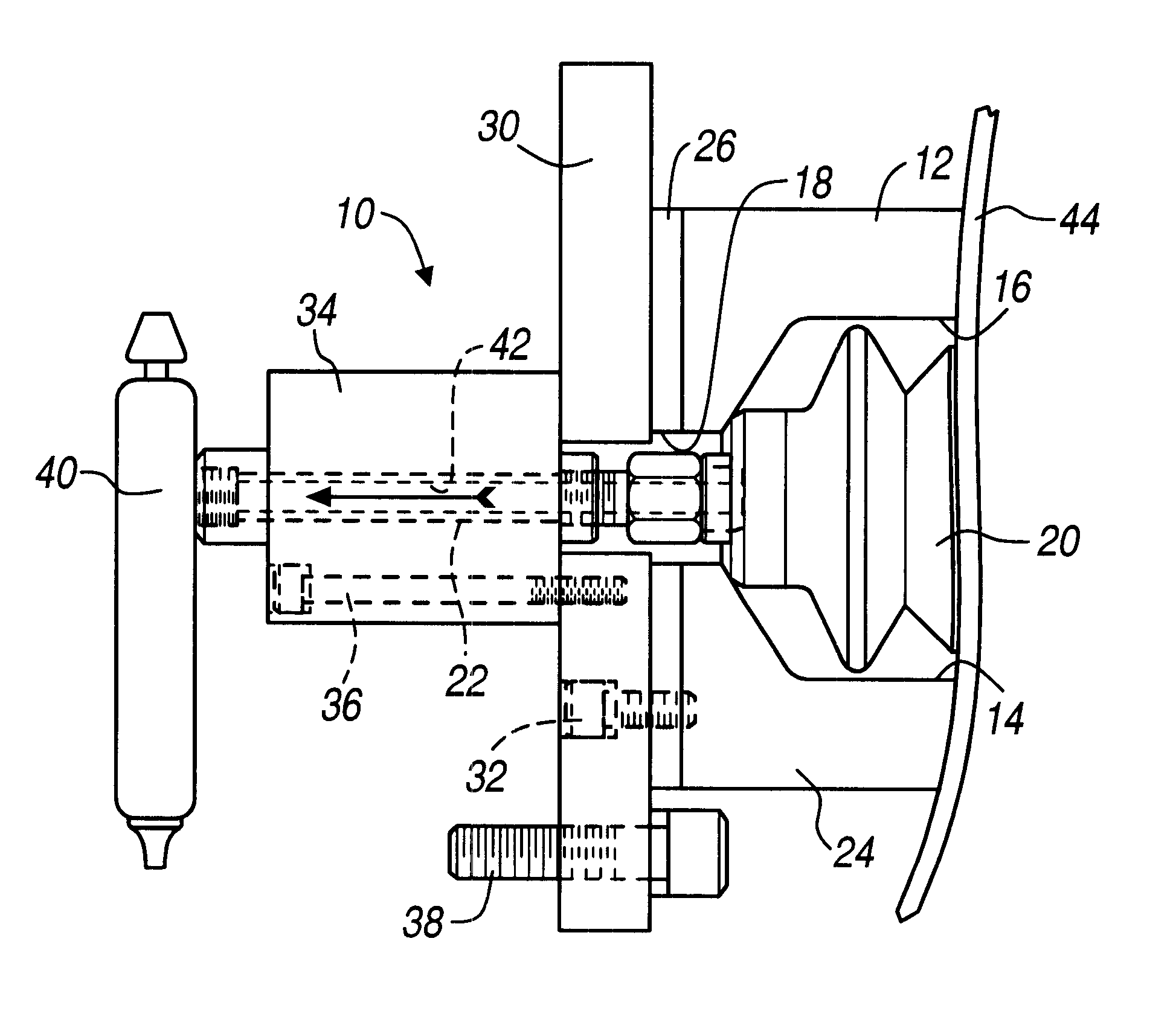
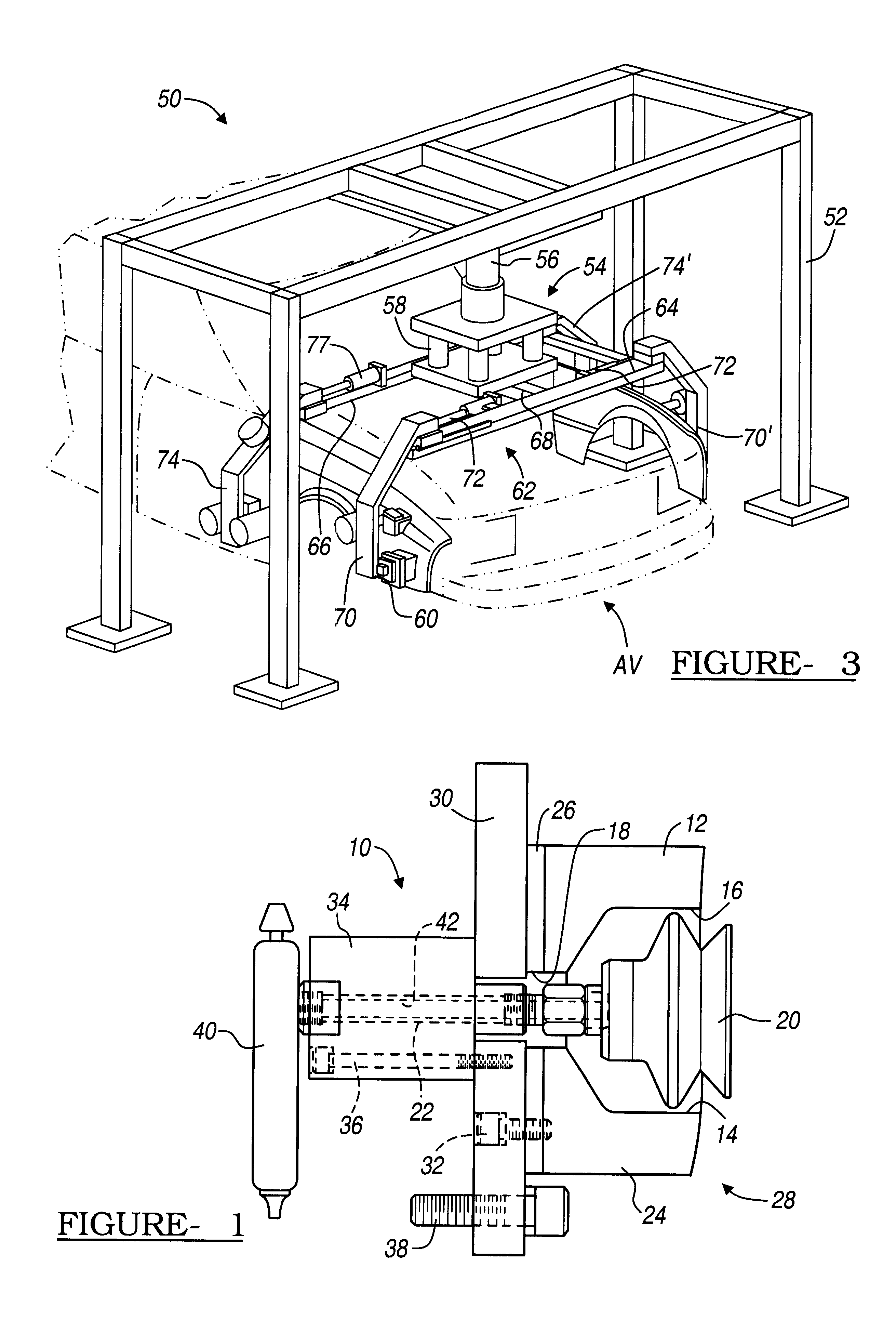
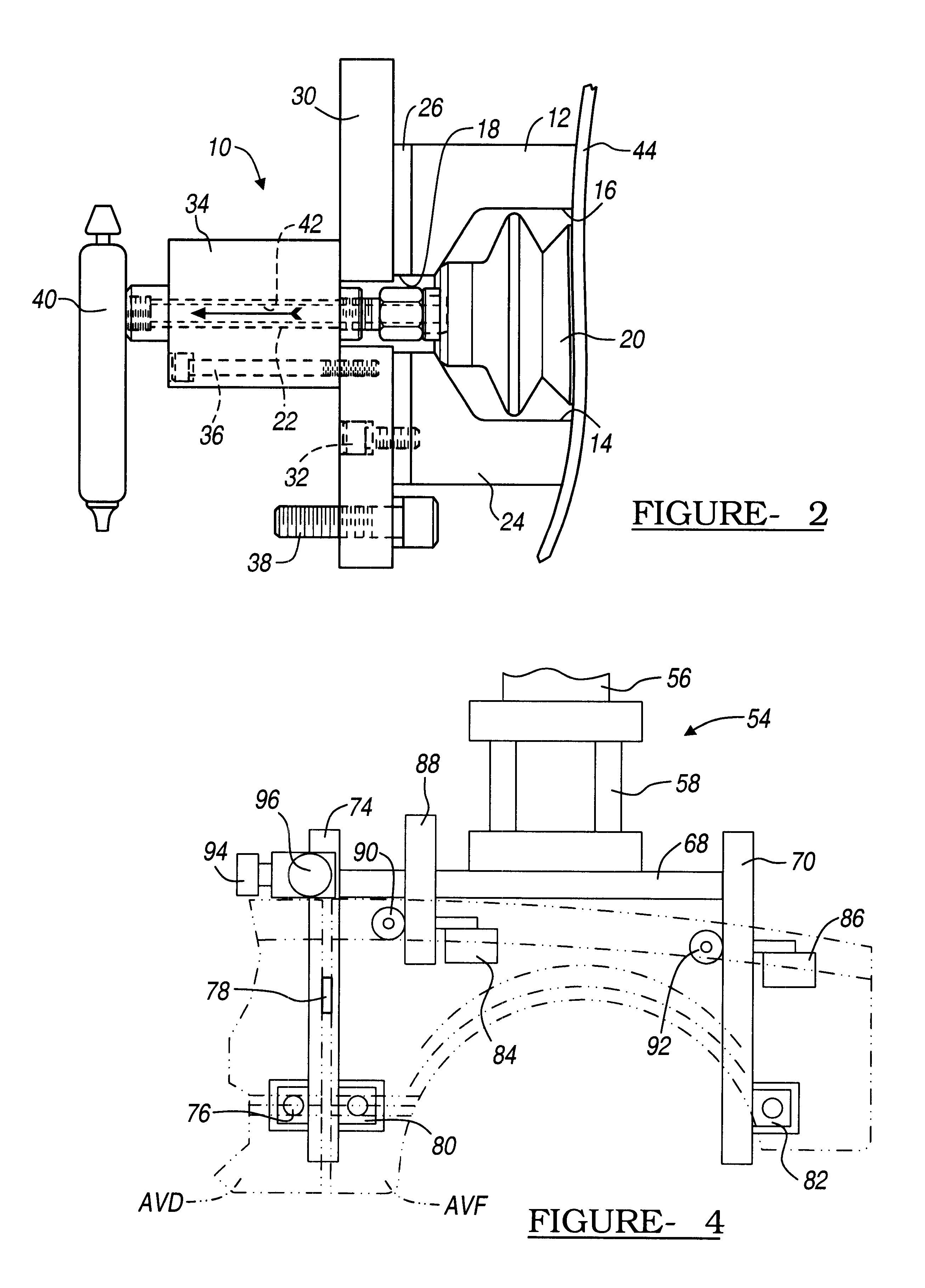
Referring to FIG. 1, a suction cup assembly, generally illustrated as 10, is shown. The assembly 10 includes a housing 12 having a bore 14 formed therethrough. The bore 14 includes a suction cup receiving portion 16 and an operating arm portion 18. Movably positioned with the suction cup receiving portion 16 of the bore 14 is a movable suction cup 20. The suction cup 20 is mounted to an axially movable arm 22 which is axially movable through the operating arm portion 18 of the bore 14 of the housing 12. The suction cup 20 is made from a known polymerized material, such as rubber.

The housing 12 comprises two parts, namely a component-abutting boot...


PUM


Abstract

A tool for holding a component during an assembly process includes a suction cup assembly which is operatively associated with an assembly system. The assembly system includes a supporting fixed frame and a movable subframe. The suction cup assembly is attached to the movable subframe by a movable arm. Each suction cup assembly includes a housing fixed to the movable arm and a suction cup movably positionable within part of a bore formed through the housing. A suction cup driver is provided to selectively and axially position the cup with respect to the housing. The housing comprises a component-abutting boot and a base. The boot includes a face which is contoured so as to substantially mate with the outer surface of the component being held.

Description

The present invention relates to a tool for clamping and aligning a vehicle fender or a similar object against a vehicle. More particularly, the present invention relates to a tool and method for aligning a vehicle body component, such as a door, engine hood, trunk lid, or roof against a vehicle.BRIEF DESCRIPTION OF THE PRIOR ARTIn the assembly of an automotive vehicle, body components are often difficult to correctly attach to the vehicle. The reason for such difficulty is generally founded in the fact that automobile components such as fenders, trunk lids, engine hoods, and roofs tend to be bulky and difficult to attach. In part due to their bulk, these components are generally difficult to align on the vehicle in that their sheer size often leads to their flexing during the assembly operation. The result of such flexing unfortunately results in a poorly fitted fender.During the early days of automobile manufacture when vehicle components such as fenders were more akin to mud flap...

Claims


Application Information

Patent Timeline
IPC IPC(8): B25B11/00B25J15/00B25J9/02B62D65/16B62D65/00
CPCB25B11/007B25J9/026B62D65/16B25J15/0052Y10T29/53974B62D65/026
Inventor PASQUE, CHARLES R.
Owner PASLIN COMPANY THE
Learn More