Drawer-type line thermal printer

a thermal printer and drawing-type technology, applied in the field of printers, can solve the problems of easy breakage, exposed thermal head, and inability to meet the needs of human body, and avoid the possibility of thermal head coming into contact with human body

Inactive Publication Date: 2002-10-22
SEIKO INSTR INC
View PDF1 Cites 5 Cited by
  • Summary
  • Abstract
  • Description
  • Claims
  • Application Information

AI Technical Summary

Problems solved by technology

A conventional thermal printer with the above-mentioned opening/closing structure has a problem in that the thermal head is exposed during operations frequently conducted by a user such as the loading of recording pap

Method used


Image

  • Drawer-type line thermal printer
  • Drawer-type line thermal printer
  • Drawer-type line thermal printer

Examples


Embodiment Construction

The details of a preferred embodiment of the present invention are described with reference to the figures as follows.

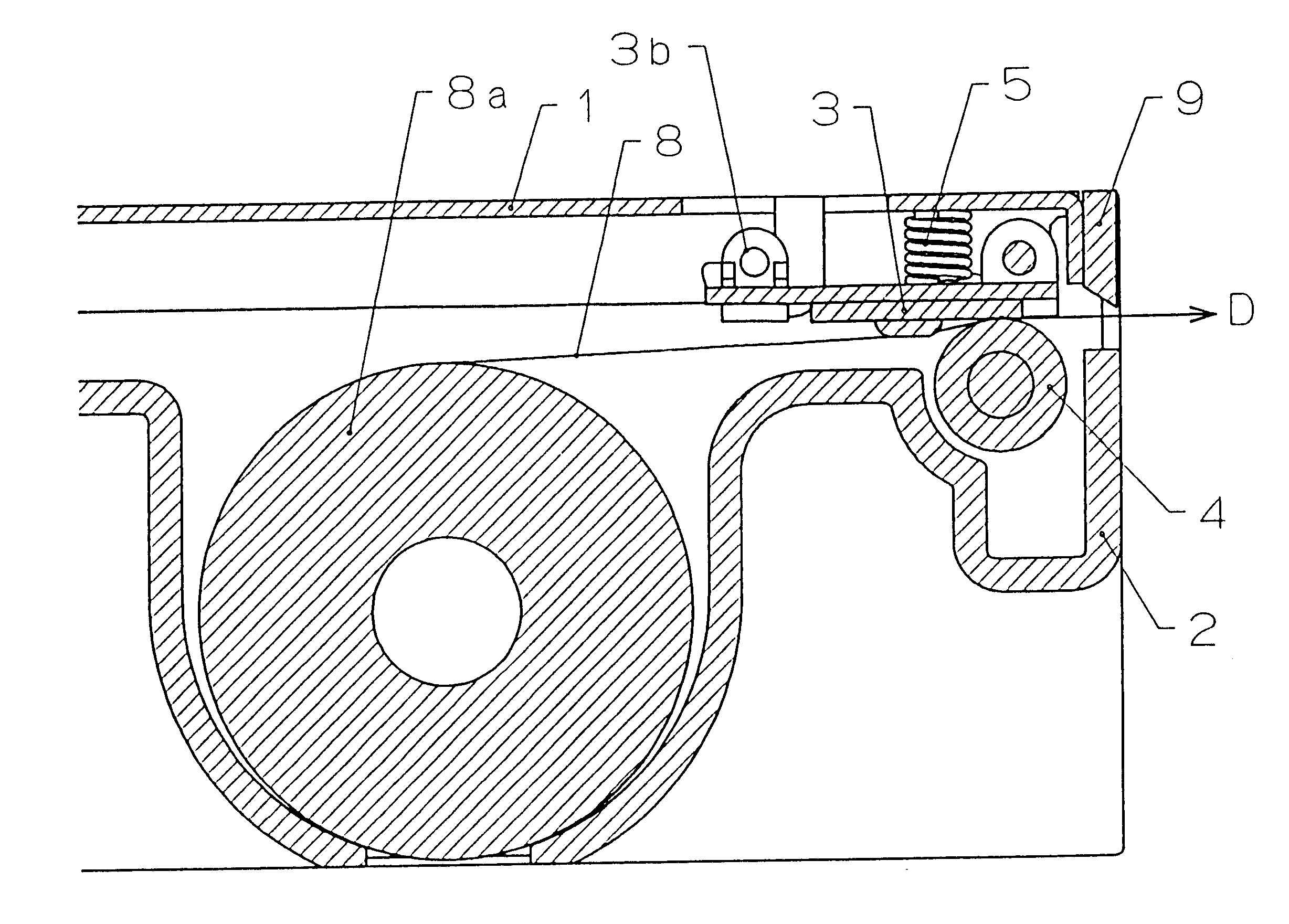
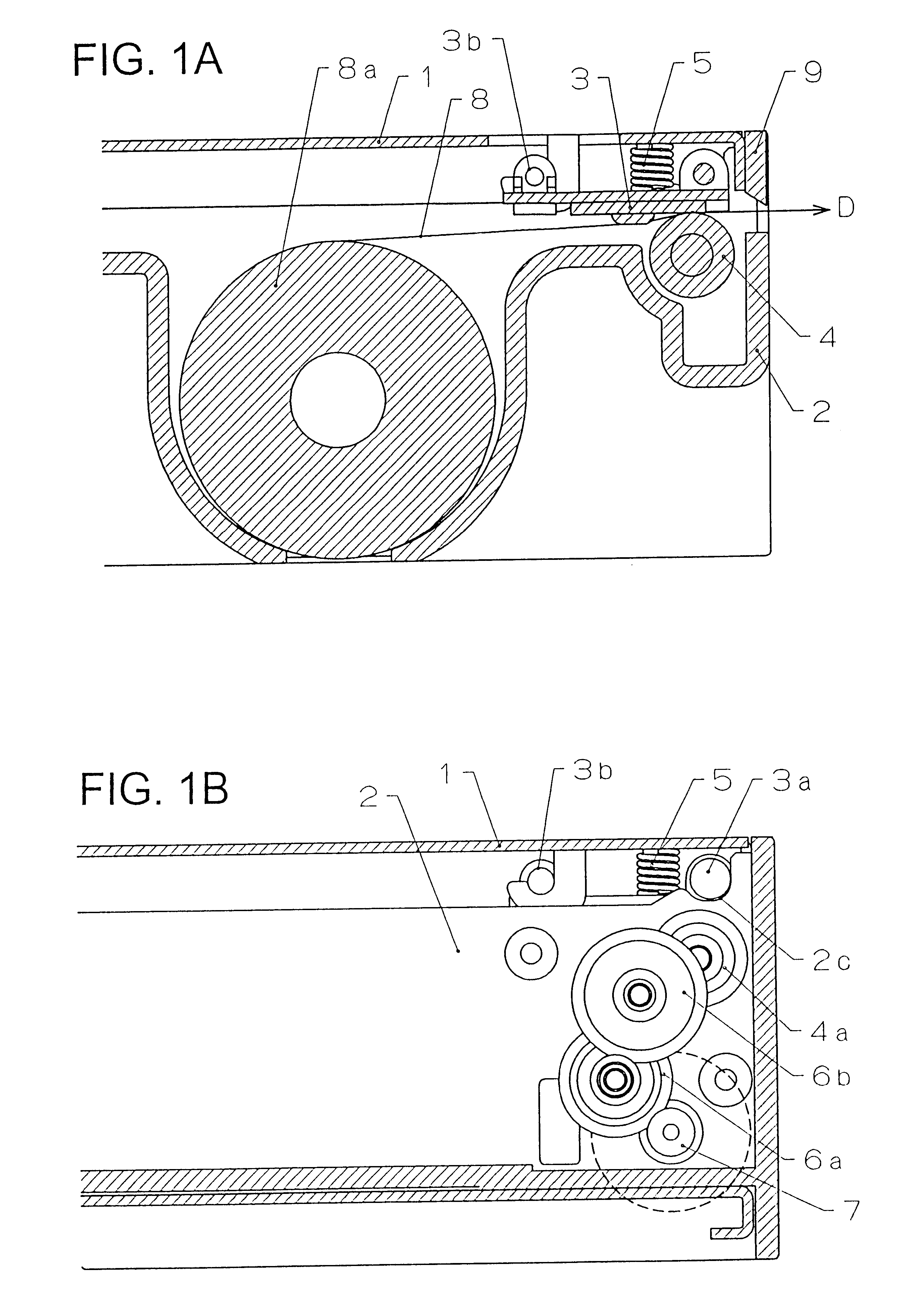
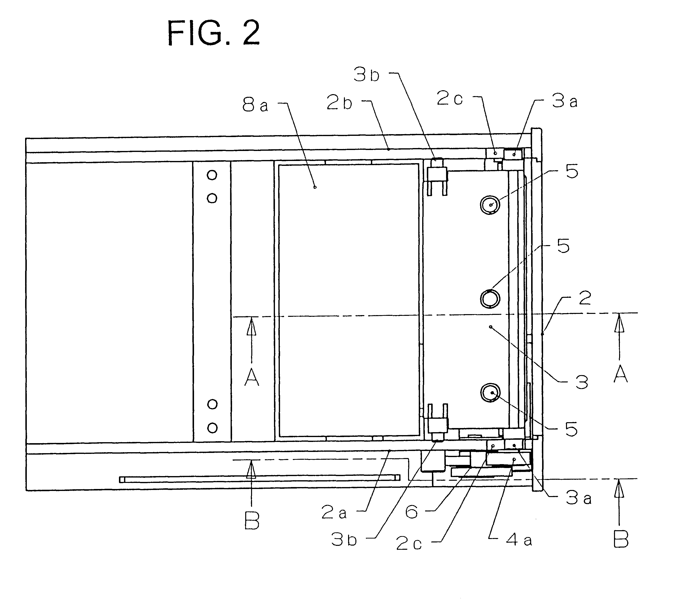
FIG. 1 shows explanatory side views illustrating an embodiment of the present invention; FIG. 1A is a sectional side view taken along line A--A shown in FIG. 2; and FIG. 1B is a sectional side view taken along line B--B shown in FIG. 2. FIG. 2 is a partially perspective plan view showing the whole apparatus. FIGS. 3 and 4 depict operations of respective parts upon opening and closing a second frame 2; FIGS. 3A and 4A are sectional side views taken along line A--A shown in FIG. 2; and FIGS. 3B and 4B are sectional side views taken along line B--B shown in FIG. 2. FIG. 5 is a perspective outview depicting the whole shape of a thermal printer according to the present invention. FIG. 6 is a conceptual view of a clamshell-type printer that has become widespread. FIGS. 1, 3, and 4 show main parts, as sectional views, of the thermal printer of the embodiment described here ...


PUM


Abstract

In a thermal printer with a drawer-type paper holder, a means is provided, which facilitates the loading of recording paper, reduces the number of parts, and improves the precision in positioning a thermal head and a platen roller, a thermal printer is composed of a first frame 1 by which the thermal head 3 is rotatably supported so that recording paper 8 is brought into pressure contact with a platen roller 4 by a biasing member 5 and a second frame 2 that pivotably supports the platen roller 4, is opened and closed in parallel to the first frame 1, and contains a recording rolled paper 8a. The thermal printer has a configuration in which a first cam 3a provided in the thermal head 3 is guided by a second cam 2c formed in the second frame 2 while being biased by the biasing member 5 and thus the platen roller 4 pivotably supported to the second frame 2 is positioned with respect to the thermal head 3.

Description

1. Field of the InventionThe present invention relates to a printer and further a mechanism of separating a platen roller and a thermal head when recording paper is sandwiched between a print head and the platen roller while the print head is brought into pressure contact with the platen roller. Particularly, the present invention relates to a drawer-type thermal printing apparatus (a thermal printer) with improved operability in loading recording paper.2. Description of the Related ArtThere has been an opening / closing structure in which opening and closing are operated by rotational movement of part of a paper holder 10 as shown in FIG. 6, as a structure in which a platen roller is separated from a thermal head considerably and thereby the loading of recording paper is facilitated. The opening / closing structure has become widespread and is characterized in that maintenance such as the loading of recording paper is carried out in a state where the paper holder 10 is opened with a pl...

Claims


Application Information

Patent Timeline
IPC IPC(8): B41J11/02B41J11/14B41J15/04B41J11/04B41J29/02B65H16/02B65H20/02
CPCB41J11/04B41J11/14B41J15/042B41J29/026
Inventor SEKIYA, HIROAKI
Owner SEIKO INSTR INC
Why Eureka
Try Eureka